Raspberry Pi 3 model Bが入手できました (7) 温度を測る
■温度を測るサンプル・プログラムtempsensor
サンプル・プログラムtempsensorのMainPageの内容を確認します。このプログラムはmcp3002、mcp3008、mcp3208の3種類のデバイスに対応するために列挙型(enum)のリストを定義します。
| enum ADCChip { mcp3002, // 2 channel 10 bit mcp3008, // 8 channel 10 bit mcp3208 // 8 channel 12 bit } |
この列挙子リストの定義の処理の後、次のMainPage()で実際のユーザ作成のプログラムの処理が始まります。システムが用意するフォームのコンポーネントの初期化を行っています。なぜ同じ命令が2行あるのかまだ調べが終わっていません。しばらくはサンプル通り使用します。
次の timer = new DispatcherTimer(); の命令でタイマを作成し、timer.Interval = TimeSpan.FromMilliseconds(500);で500msのインターバルを決めます。
次の timer.Tick += Timer_Tick; でタイマのイベントごとに関数 Timer_Tick; が呼び出されるようになります。そのあと timer.Start(); が開始されます。
|
public MainPage() |
この処理の後、whichADCChipにmcp3208のデバイスをセットし、switch()関数で該当するデバイスに対する処理を設定しています。ここでは最後のmcp3208の処理にジャンプし、読み書きのための3バイトのバッファ・データを定義しています。
| whichADCChip = ADCChip.mcp3208; switch (whichADCChip) { case ADCChip.mcp3002: { // To line everything up for ease of reading back (on byte boundary) we // will pad the command start bit with 1 leading "0" bit // Write 0SGO MNxx xxxx xxxx // Read ???? ?N98 7654 3210 // S = start bit // G = Single / Differential // O = Chanel data // M = Most significant bit mode // ? = undefined, ignore // N = 0 "Null bit" // 9-0 = 10 data bits // 0110 1000 = 1 0 pad bit, start bit, Single ended, odd (channel 0), MSFB only, 2 clocking bits // 0000 0000 = 8 clocking bits readBuffer = new byte[2] { 0x00, 0x00 }; writeBuffer = new byte[2] { 0x68, 0x00 }; } break; case ADCChip.mcp3008: { // To line everything up for ease of reading back (on byte boundary) we // will pad the command start bit with 7 leading "0" bits // Write 0000 000S GDDD xxxx xxxx xxxx // Read ???? ???? ???? ?N98 7654 3210 // S = start bit // G = Single / Differential // D = Chanel data // ? = undefined, ignore // N = 0 "Null bit" // 9-0 = 10 data bits // 0000 01 = 7 pad bits, start bit // 1000 0000 = single ended, channel bit 2, channel bit 1, channel bit 0, 4 clocking bits // 0000 0000 = 8 clocking bits readBuffer = new byte[3] { 0x00, 0x00, 0x00 }; writeBuffer = new byte[3] { 0x01, 0x80, 0x00 }; } break; case ADCChip.mcp3208: InitSPI(); |
最後にInitSPI()のSPI処理の初期化を行い、MainPage()関数の処理を終わります。後は、タイマのイベントの発生ごとにTimer_Tick()の関数が呼び出されます。
●タイマ・イベントが発生すると
500ms間隔のイベントが発生すると、次の関数が起動し、DisplayTextBoxContents();関数を呼び出します。
| private void Timer_Tick(object sender, object e) { DisplayTextBoxContents(); } |
●読み取った値の表示処理の関数
DisplayTextBoxContents()関数では、MainPage 関数で定義したwriteBufferのデータをコマンドおよびダミー・データとして書き込み、readBufferにmcp3208からのデータをセットします。そのあと、convertToInt(readBuffer);関数で受信データからアナログ入力データの値を得ます。そのあと、アナログ入力データの値を文字列として画面表示のための変数に渡します。
| public void DisplayTextBoxContents() { SpiDisplay.TransferFullDuplex(writeBuffer, readBuffer); res = convertToInt(readBuffer); textPlaceHolder.Text = res.ToString(); } |
●アナログ入力データの処理
アナログ入力値は整数変数 resultにセットされます。ここでもswitch()関数で該当する処理にジャンプします。
|
public int convertToInt(byte[] data) case ADCChip.mcp3208: |
最初に読み込んだ値を8ビット・シフトし、次の読み込んだ値を加算して12ビットのアナログ入力データを得ています。return result;で計算し得られた入力値を関数の戻り値としています。
MainPage.Xaml.csの最後は次の各変数などの定義で終わります。このプログラムはRaspberry Pi 2を前提にしていますが、Raspberry Pi 3でも問題なく動作しました。
| /*RaspBerry Pi2 Parameters*/ private const string SPI_CONTROLLER_NAME = "SPI0"; /* For Raspberry Pi 2, use SPI0 */ private const Int32 SPI_CHIP_SELECT_LINE = 0; /* Line 0 maps to physical pin number 24 on the Rpi2 */ byte[] readBuffer = null; /* this is defined to hold the output data*/ byte[] writeBuffer = null; /* we will hold the command to send to the chipbuild this in the constructor for the chip we are using */ private SpiDevice SpiDisplay; // create a timer private DispatcherTimer timer; int res; } } |
SPIインターフェースの初期化を行っているprivate async void InitSPI()関数は省略しましたが、プログラムの流れを概観してみました。
このプログラムでは、アナログ入力値をそのまま表示しています。センサを接続した場合はアナログ・センサからの入力値を測定値へ変換する計算を追加します。
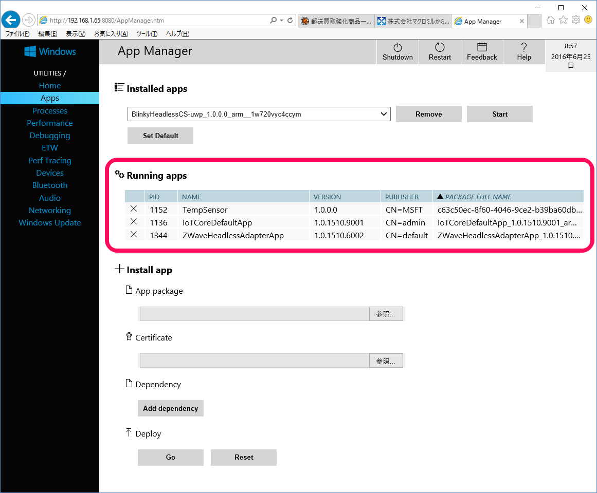
●デバッグ中もDevice PortalでWindows 10 IOT Coreの稼働状況が確認できる
デバッグ中も、次に示すようにDevice PortalでRaspberry Pi 2上のWindows 10 IOT Coreにインストールされているアプリを表示することができます。
プロセスを確認すると次に示すように、各プロセスの稼働状況を確認することができます。
デバッグ中のTempSensor.exeが表示されています。
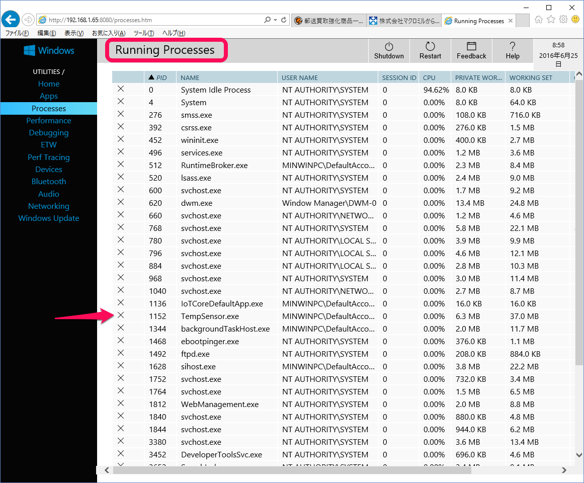
Raspberry PiがWindows 10 IOT Coreの管理下で稼働していることがよくわかります。
(2016/6/26 V1.0)
<神崎康宏>
バックグラウンド列挙型;整数型の定数をカンマで区切って定数リストを定義します。switch制御文を使うときに便利です。
8ビット・シフト;MCP3208は12ビットのA-D変換値を、8ビットを扱うSPIインターフェースで2回に分けて送ってきます(データシートの図6-1、図6-2参照)。