フルカラー7セグメントLEDの点灯①接続
NeoPixelと呼ばれるRGBが一つになったLEDがあります。この一つのLEDを7セグメントの一つのエレメントに加工したのが、
フルカラー7セグメントLED表示器 文字高1インチ(I-12181)
です。秋月電子通商から入手しました。NeoPixelは、1個で使われるより、複数をつなぐ製品が多いです。
●おもなスペック
- 電源電圧 3.5~5.3V
- マイコン内蔵LED(WS2812B)
- 外形 34×24mm
特徴は、1セグメントごとにフルカラーLEDを搭載し、0~255でR、G、Bの輝度の設定ができます。
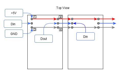
●接続
+5VとGNDは、それぞれ2ピンあって、全部パラレルに接続します。信号は、Dinピンに入れ、Doutから次のDinへつなぎます。次の接続図は、数字が見える側から見た図です。ピンは裏側に、それぞれ6本出ています。
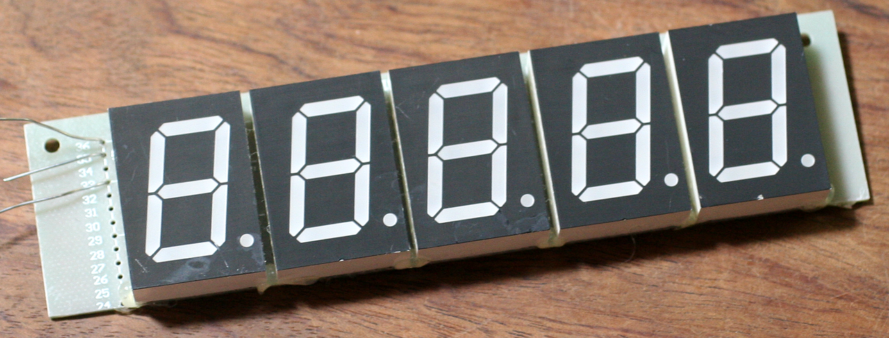
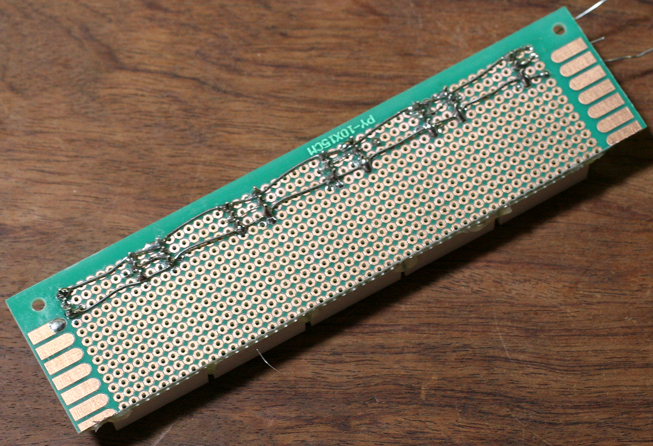
6個の7セグメントLEDを接続しました。
●Arduino UNOとの接続
多くのエレメントを光らすと電流がそれなりに流れるので、+5Vはエネループ(4本;4.8V)を使いました。5Vを使うので、マイコンはArduino UNOです。
| Arduino | 7セグメントLED | エネループ |
|---|---|---|
| 6ピン(直列に470Ω) | Din | |
| +5V | + | |
| GND | GND | ー |
●スケッチ
ライブラリを管理から、NeoPixelで検索します。必要なのは、Adafruit NeoPixelです。別のスケッチの開発時にAdafruit DMA neopixel libraryを入れています。
スケッチ例-Adafruit NeoPixelからsimpleを読み込んでコンパイル、実行します。
緑色で、二つの7セグメントの各エレメントを点灯していきます。
#define NUMPIXELS 16
16を48に変更します。6個の7セグメントLEDのエレメントを点灯していきました。NUMPIXELSの数値は、エレメント一つに対応していることがわかります。
#define DELAYVAL 500
500を1に変更しました。1エレメントを0.5秒ずつ表示していたのが、描画の様子がわからないくらいの素早い表示になりました。
pixels.setPixelColor(i, pixels.Color(0, 150, 0))
pixels.Color(0, 150, 0)をpixels.Color(0, 0, 50)に変更しました。R、G、Bの順で輝度をしてしますから、緑が青色になりました。
pixels.Color(100, 100, 100)に変更すると、白色になりました。
// NeoPixel Ring simple sketch (c) 2013 Shae Erisson
// Released under the GPLv3 license to match the rest of the
// Adafruit NeoPixel library

#include  <Adafruit_NeoPixel.h>
#ifdef __AVR__
 #include <avr/power.h> // Required for 16 MHz Adafruit Trinket
#endif

// Which pin on the Arduino is connected to the NeoPixels?
#define PIN        6 // On Trinket or Gemma, suggest changing this to 1

// How many NeoPixels are attached to the Arduino?
#define NUMPIXELS 48 // Popular NeoPixel ring size

// When setting up the NeoPixel library, we tell it how many pixels,
// and which pin to use to send signals. Note that for older NeoPixel
// strips you might need to change the third parameter -- see the
// strandtest example for more information on possible values.
Adafruit_NeoPixel pixels(NUMPIXELS, PIN, NEO_GRB + NEO_KHZ800);

#define DELAYVAL 1 // Time (in milliseconds) to pause between pixels

void setup() {
  // These lines are specifically to support the Adafruit Trinket 5V 16 MHz.
  // Any other board, you can remove this part (but no harm leaving it):
#if defined(__AVR_ATtiny85__) && (F_CPU == 16000000)
  clock_prescale_set(clock_div_1);
#endif
  // END of Trinket-specific code.

  pixels.begin(); // INITIALIZE NeoPixel strip object (REQUIRED)
}

void loop() {
  pixels.clear(); // Set all pixel colors to 'off'

  // The first NeoPixel in a strand is #0, second is 1, all the way up
  // to the count of pixels minus one.
  for(int i=0; i<NUMPIXELS; i++) { // For each pixel...

    // pixels.Color() takes RGB values, from 0,0,0 up to 255,255,255
    // Here we're using a moderately bright green color:
    pixels.setPixelColor(i, pixels.Color(100, 100, 100));

    pixels.show();   // Send the updated pixel colors to the hardware.

    delay(DELAYVAL); // Pause before next pass through loop
  }

}
pixels.show();をループの外に出します(50行に移動)。今度は、描画ルーチンが書き終わってshow表示するので、ちらつきがなくなりました。