初めてのArduino ① UNOボードとIDE2.0
Arduino UNOは何度かのマイナー・アップデート後Arduino UNO R3になって約10年弱経ちました。Arduino UNO R3になっても、コネクタが一体型になったり、I/Oピンの内側にピンの名称が印刷されたりと、気がつかないほどの変化があります。2022年の初めには、全体が半分の縮尺になったArduino Uno Mini Limited Editionが出ましたが、特筆するような機能はないようです。
●IDE(統合開発環境)
2022年当初の開発環境はArduino IDE 1.8.19です。これより古いバージョンは早急にアップデートしておきます。logソフトに重大なセキュリティ上のバグがありました。
ここ数年、IDEにバージョン2がアナウンスされています。ベータ版も長く、現在は、Arduino IDE 2.0 RC(2.0.0-rc5)です。このrc5からは、自動更新の機能が入りました。RCとはもうすぐ正式版ですというバージョンですが、すでに半年ほど製品版にはなっていません。
特徴は、次のように書かれています。
より高速でさらに強力です。より最新のエディターとより応答性の高いインターフェースに加えて、オートコンプリート、コードナビゲーション、さらにはライブデバッガも備えています。
エディタでプログラムを入力しているとき、文法的におかしい、つまり、コンパイルするとエラーになる場所には、赤色のアンダーラインが引かれます。この機能は、コードナビゲーションなのかもしれません。解説したページは見つかりません。
●利用するのはArduino UNO R3とArduino IDE 2.0 RC(2.0.0-rc5)
最新版のハードとソフトを使って、アプリケーションを作っていきます。
Arduino UNO R3とPCをUSBケーブルでつなぎ、Arduino IDE 2.0 RC(2.0.0-rc5)を立ち上げます。最初にするのは、ボードの選択とCOMポートの選択です。
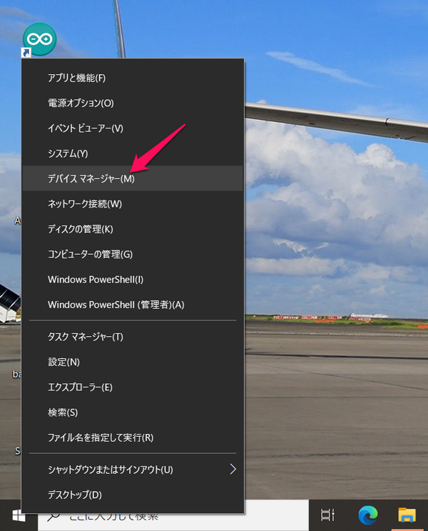
Windowsのスタートアイコンを右クリックして、デバイスマネージャを選びます。
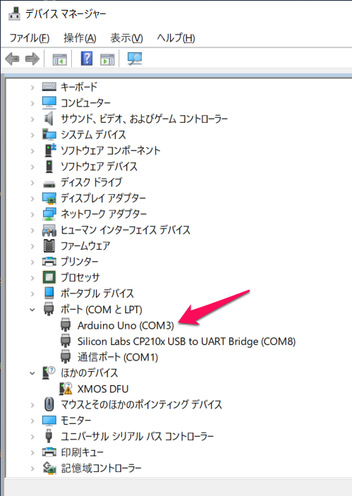
ポート(COMとLPT)にArduino Uno(COM3)を見つけます。
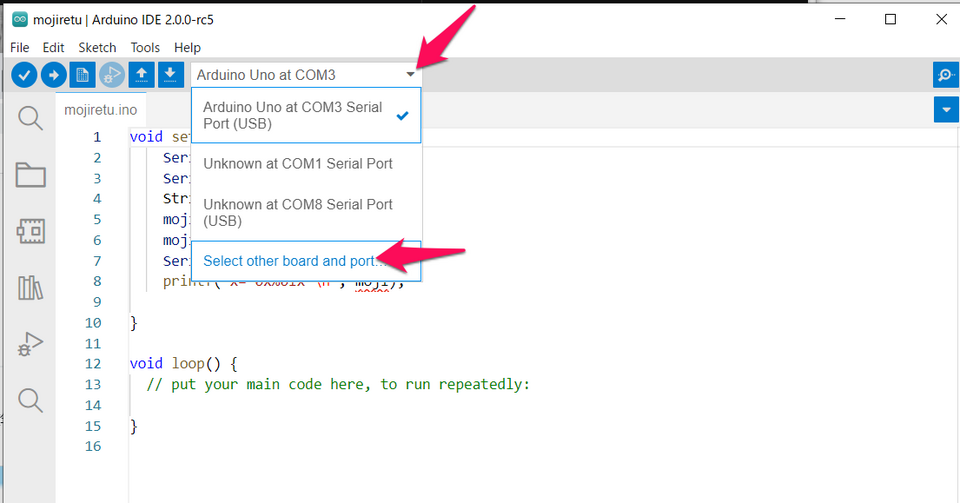
IDE画面です。自動で、ボードが選択されていることもあります。Select other board and portをクリックします。
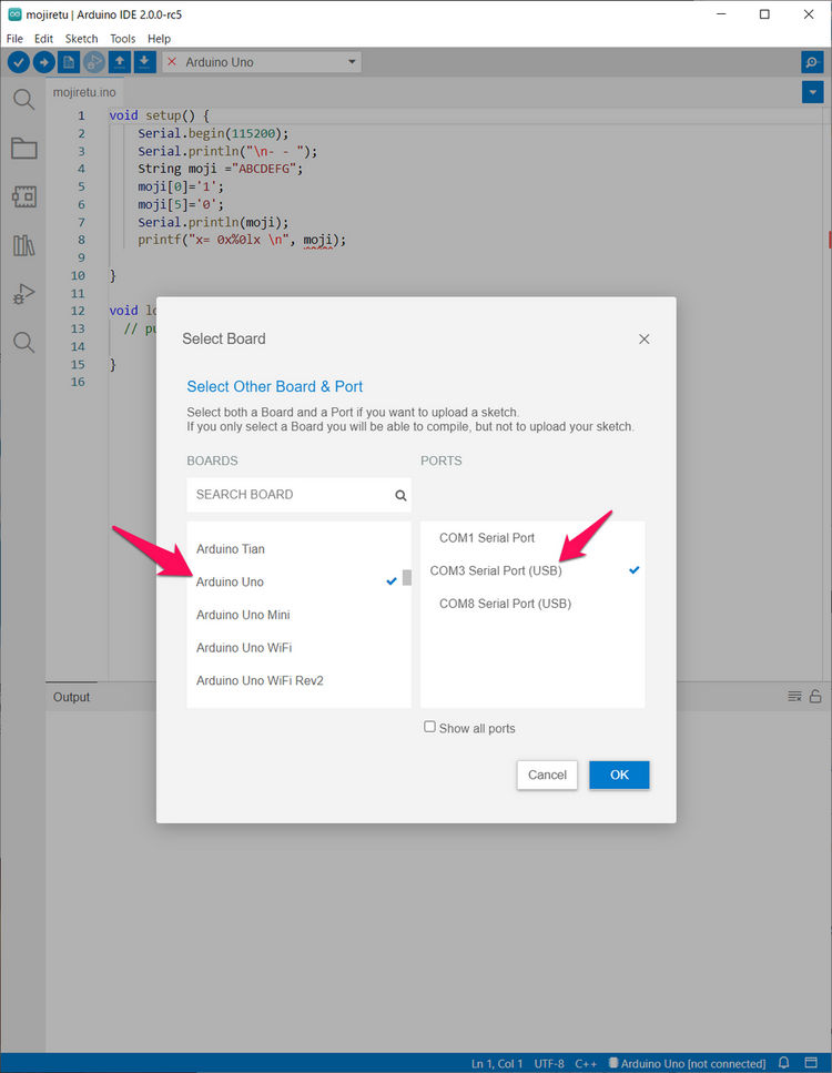
この画面で、左のボード一覧からArduino Unoを選らび、COM3 Serial Port(USB)を選びます。COMポートが出てこないときは、IDEを一度終了し、USBケーブルをさし直して、目的のCOMポートが表示されることを確認します。
スケッチを書き始める準備ができました。
●Lチカ
動作確認にために、Lチカ=LEDチカチカを行います。プログラムは、サンプルに入っているBlinksを使います。と思ったのですが、2.0のチュートリアルBlink Without Delayからコピペしてきます。
/*
  Blink without Delay

  Turns on and off a light emitting diode (LED) connected to a digital pin,
  without using the delay() function. This means that other code can run at the
  same time without being interrupted by the LED code.

  The circuit:
  - Use the onboard LED.
  - Note: Most Arduinos have an on-board LED you can control. On the UNO, MEGA
    and ZERO it is attached to digital pin 13, on MKR1000 on pin 6. LED_BUILTIN
    is set to the correct LED pin independent of which board is used.
    If you want to know what pin the on-board LED is connected to on your
    Arduino model, check the Technical Specs of your board at:
    https://www.arduino.cc/en/Main/Products

  created 2005
  by David A. Mellis
  modified 8 Feb 2010
  by Paul Stoffregen
  modified 11 Nov 2013
  by Scott Fitzgerald
  modified 9 Jan 2017
  by Arturo Guadalupi

  This example code is in the public domain.

  https://www.arduino.cc/en/Tutorial/BuiltInExamples/BlinkWithoutDelay
*/

// constants won't change. Used here to set a pin number:
const int ledPin =  LED_BUILTIN;// the number of the LED pin

// Variables will change:
int ledState = LOW;             // ledState used to set the LED

// Generally, you should use "unsigned long" for variables that hold time
// The value will quickly become too large for an int to store
unsigned long previousMillis = 0;        // will store last time LED was updated

// constants won't change:
const long interval = 1000;           // interval at which to blink (milliseconds)

void setup() {
  // set the digital pin as output:
  pinMode(ledPin, OUTPUT);
}

void loop() {
  // here is where you'd put code that needs to be running all the time.

  // check to see if it's time to blink the LED; that is, if the difference
  // between the current time and last time you blinked the LED is bigger than
  // the interval at which you want to blink the LED.
  unsigned long currentMillis = millis();

  if (currentMillis - previousMillis >= interval) {
    // save the last time you blinked the LED
    previousMillis = currentMillis;

    // if the LED is off turn it on and vice-versa:
    if (ledState == LOW) {
      ledState = HIGH;
    } else {
      ledState = LOW;
    }

    // set the LED with the ledState of the variable:
    digitalWrite(ledPin, ledState);
  }
}
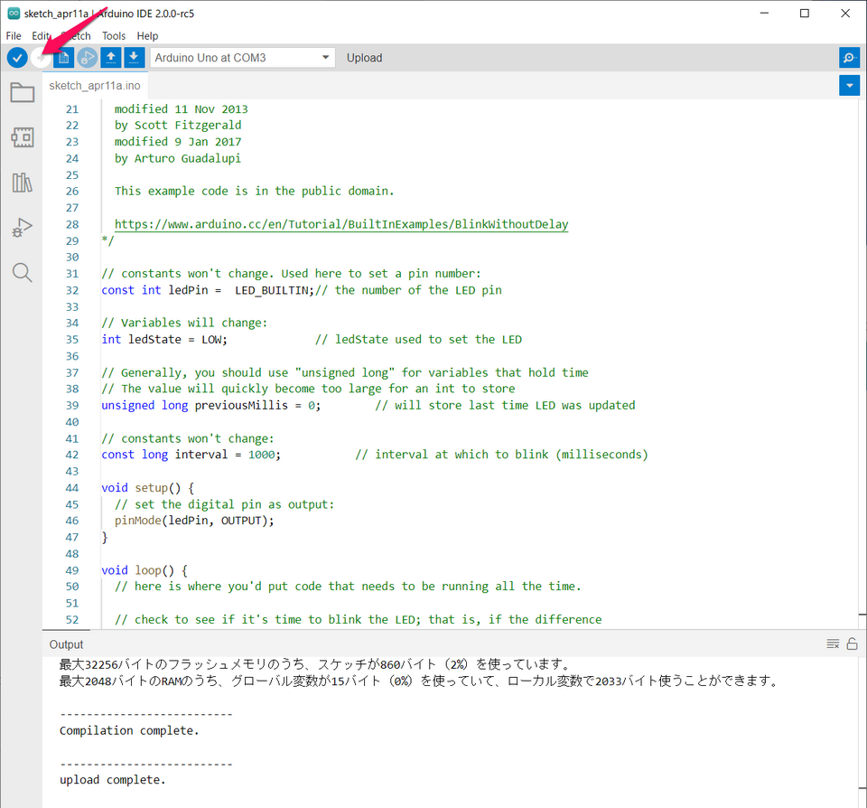
新規を選び、貼り付けます。「->」でコンパイルします。
Lチカしました。13とシルク印刷されたLというオレンジ色のLEDが1秒間間隔で点滅しています。
const int ledPin = LED_BUILTIN
は、Arduino UNOでは13番です。constは定数の指定で、通常ROM領域に置かれます。UNOでそうなるかは不明です。intは整数型です。Arduinoのマイコンによっては長さが異なります。int16_tと記述すると、確実に16ビットの整数になります。16ビットで1ビットを指定しているのはなんだかもったいないです。int8_tとしても何ら問題ありません。
◆const int
最大32256バイトのフラッシュメモリのうち、スケッチが860バイト(2%)を使っています。
最大2048バイトのRAMのうち、グローバル変数が15バイト(0%)を使っていて、ローカル変数で2033バイト使うことができます。
◆const int16_t
最大32256バイトのフラッシュメモリのうち、スケッチが860バイト(2%)を使っています。
最大2048バイトのRAMのうち、グローバル変数が15バイト(0%)を使っていて、ローカル変数で2033バイト使うことができます。
◆int16_t
最大32256バイトのフラッシュメモリのうち、スケッチが860バイト(2%)を使っています。
最大2048バイトのRAMのうち、グローバル変数が15バイト(0%)を使っていて、ローカル変数で2033バイト使うことができます。
◆int8_t
最大32256バイトのフラッシュメモリのうち、スケッチが860バイト(2%)を使っています。
最大2048バイトのRAMのうち、グローバル変数が15バイト(0%)を使っていて、ローカル変数で2033バイト使うことができます。
いずれも、メモリの使用量に変化はありませんでした。
LOWとHIGHはArduino言語(C++)の予約語です。LOW=0、HIGH=1です。
I/Oポート、ここでは13番は、setup()内で、pinMode(ledPin, OUTPUT);と出力の指定をしています。ここでは出てきませんが、pinMode()ではINPUTの指定をすると、入力になります。
millis()は、Arduino特有な関数で、プログラムの実行を開始した時から現在までの時間をms単位が得られます。interval = 1000、つまり1秒をカウントします。
●13番ピンの回路の変遷
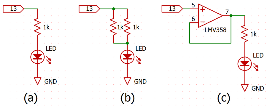
13番ピンはSPIバスの時はクロックSCK信号として使われます。通常は汎用のI/Oピンです。しかし、LEDがつながっています。
図(a)は初期のArduino UNOです。少し経過して図(b)になりました。Arduino UNO R3では、図(c)のようにOPアンプのボルテージ・フォロワ回路が追加され、13番ピンにほかの回路がつながっても影響が少なくなりました。
●環境
- Windows10 Pro 21H2
