ANALOG OUTPUT ① MKR WiFi 1010で波形生成<その2>
MKR WiFi 1010は、SAMD21(Cortex-M0+)マイコンを搭載していて、D-Aコンバータのスペックは次のとおりです。
10ビット、350ksps
前回の波形発生では、サイン波は23Hz、方形波は170kHzでした。方形波はON/OFFするだけでした。
●サイン波の周波数を上げる
検索すると、D-Aコンバータを直接制御する方法が見つかりました。Arduino MKR Zero用ですが、MKR WiFi 1010と同じCPUのはずです。アナログ出力のポートを変更しました。
Arduino Zero DAC Overview and Waveform Generator Example
//***************ZeroDACExample Sketch*******************************
//https://forcetronic.blogspot.com/search?q=Arduino+Zero+DAC+
//This sketch provides an example on using the DAC on the Arduino Zero.
//It was used in a video tutorial on the ForceTronics YouTube Channel.
//This code is free and open for anybody to use and modify at their own risk

volatile int sIndex; //Tracks sinewave points in array
int sampleCount = 100; // Number of samples to read in block
int *wavSamples; //array to store sinewave points
uint32_t sampleRate = 1000; //sample rate of the sine wave

void setup() {
  analogWriteResolution(10); //set the Arduino DAC for 10 bits of resolution (max)
  getSinParameters(); //get sinewave parameters from user on serial monitor

  /*Allocate the buffer where the samples are stored*/
  wavSamples = (int *) malloc(sampleCount * sizeof(int));
  genSin(sampleCount); //function generates sine wave
}

void loop() {
  sIndex = 0;   //Set to zero to start from beginning of waveform
  tcConfigure(sampleRate); //setup the timer counter based off of the user entered sample rate
  //loop until all the sine wave points have been played
  while (sIndex<sampleCount)
  {
 //start timer, once timer is done interrupt will occur and DAC value will be updated
    tcStartCounter();
  }
  //disable and reset timer counter
  tcDisable();
  tcReset();
}

//This function generates a sine wave and stores it in the wavSamples array
//The input argument is the number of points the sine wave is made up of
void genSin(int sCount) {
 const float pi2 = 6.28; //2 x pi
 float in;

 for(int i=0; i<sCount;i++) { //loop to build sine wave based on sample count
  in = pi2*(1/(float)sCount)*(float)i; //calculate value in radians for sin()
  wavSamples[i] = ((int)(sin(in)*511.5 + 511.5)); //Calculate sine wave value and offset based on DAC resolution 511.5 = 1023/2
 }
}

//This function handles getting and setting the sine wave parameters from
//the serial monitor. It is important to use the Serial.end() function
//to ensure it doesn't mess up the Timer counter interrupts later
void getSinParameters() {
  Serial.begin(115200);
  Serial.println("Enter number of points in sine wave (range 10 to 1000)");
  sampleCount = readParameter();
  if (sampleCount < 10 || sampleCount > 1000) sampleCount = 100;
  Serial.print("Sample count set to ");
  Serial.println(sampleCount);
  Serial.println("Enter sample rate or samples per second for DAC (range 1 to 100k)");
  sampleRate = readParameter();
  if (sampleRate < 1 || sampleRate > 100000) sampleRate = 10000;
  Serial.print("Sample rate set to ");
  Serial.println(sampleRate);
  Serial.println("Generating sine wave........");
  Serial.end();
}

//waits for serial data and reads it in. This function reads in the parameters
// that are entered into the serial terminal
int readParameter() {
 while(!Serial.available());
 return Serial.parseInt(); //get int that was entered on Serial monitor
}

// Configures the TC to generate output events at the sample frequency.
//Configures the TC in Frequency Generation mode, with an event output once
//each time the audio sample frequency period expires.
 void tcConfigure(int sampleRate)
{
 // Enable GCLK for TCC2 and TC5 (timer counter input clock)
 GCLK->CLKCTRL.reg = (uint16_t) (GCLK_CLKCTRL_CLKEN | GCLK_CLKCTRL_GEN_GCLK0 | GCLK_CLKCTRL_ID(GCM_TC4_TC5)) ;
 while (GCLK->STATUS.bit.SYNCBUSY);

 tcReset(); //reset TC5

 // Set Timer counter Mode to 16 bits
 TC5->COUNT16.CTRLA.reg |= TC_CTRLA_MODE_COUNT16;
 // Set TC5 mode as match frequency
 TC5->COUNT16.CTRLA.reg |= TC_CTRLA_WAVEGEN_MFRQ;
 //set prescaler and enable TC5
 TC5->COUNT16.CTRLA.reg |= TC_CTRLA_PRESCALER_DIV1 | TC_CTRLA_ENABLE;
 //set TC5 timer counter based off of the system clock and the user defined sample rate or waveform
 TC5->COUNT16.CC[0].reg = (uint16_t) (SystemCoreClock / sampleRate - 1);
 while (tcIsSyncing());

 // Configure interrupt request
 NVIC_DisableIRQ(TC5_IRQn);
 NVIC_ClearPendingIRQ(TC5_IRQn);
 NVIC_SetPriority(TC5_IRQn, 0);
 NVIC_EnableIRQ(TC5_IRQn);

 // Enable the TC5 interrupt request
 TC5->COUNT16.INTENSET.bit.MC0 = 1;
 while (tcIsSyncing()); //wait until TC5 is done syncing
}

//Function that is used to check if TC5 is done syncing
//returns true when it is done syncing
bool tcIsSyncing()
{
  return TC5->COUNT16.STATUS.reg & TC_STATUS_SYNCBUSY;
}

//This function enables TC5 and waits for it to be ready
void tcStartCounter()
{
  TC5->COUNT16.CTRLA.reg |= TC_CTRLA_ENABLE; //set the CTRLA register
  while (tcIsSyncing()); //wait until snyc'd
}

//Reset TC5
void tcReset()
{
  TC5->COUNT16.CTRLA.reg = TC_CTRLA_SWRST;
  while (tcIsSyncing());
  while (TC5->COUNT16.CTRLA.bit.SWRST);
}

//disable TC5
void tcDisable()
{
  TC5->COUNT16.CTRLA.reg &= ~TC_CTRLA_ENABLE;
  while (tcIsSyncing());
}

void TC5_Handler (void)
{
  analogWrite(A0, wavSamples[sIndex]);
  sIndex++;
  TC5->COUNT16.INTFLAG.bit.MC0 = 1;
}
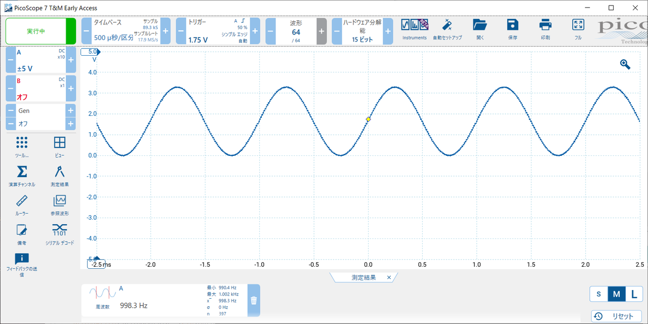
スケッチを実行し、シリアルコンソールを開きます。本来、何らかのメッセージが表示されるはずですが、筆者のモデルでは何も出ませんでした。最上部の欄に「100 100000」と入力し、送信ボタンをクリックします。
約1kHzのサイン波が得られました。