Arduino UNO R4 Minimaでセンサ・インターフェーシング ㉘ 光センサ BH1750
Adafruitから周辺光センサ BH1750(ローム)を利用します。
●AdafruitのStemma QT/Qwiicボード
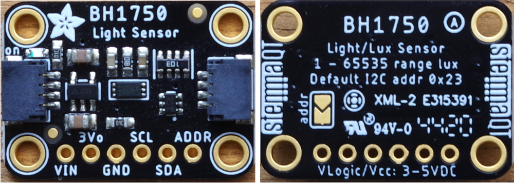
Stemma QT/Qwiic(JST SH 4ピン)コネクタは2か所に装着されていて、どちらにつないでもかまいません。このコネクタを使ってI2Cで制御する場合、特に、ジャンパ線をつなぐなどは不要です。
コネクタは、表と裏のどちらも差し込めそうですが、ピンが内部の上部に並んでいるので、差し込める方向は一意です。ロック機構はないですが、すぐに抜けるということはありません。
●光センサBH1750のおもなスペック
- 動作電圧 2.4~3.6V
- 動作温度範囲 -40~85°C
- 測定範囲 0~65,000ルクス
- インターフェース I2C(最大400kHz)
- スレーブ・アドレス 0x23(裏面のaddrをショートすることで0x5cに変更できる)
●使用環境
- Arduino UNO R4 Minima
- Arduino IDE 2.2.1
- Windows10 22H2
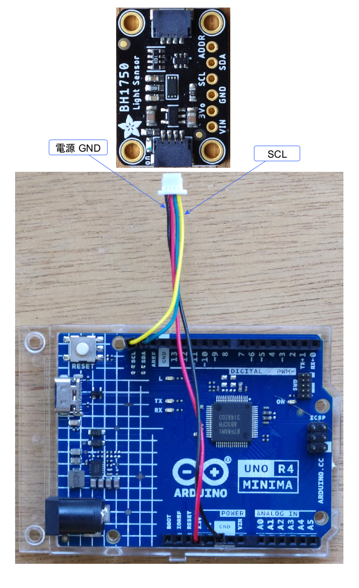
●接続
Arduino UNO R4 MinimaのI2C信号とセンサ・ボードをJSTコネクタでつなぎます(Stemma QT/Qwiicボードの写真の比率は異なる)。
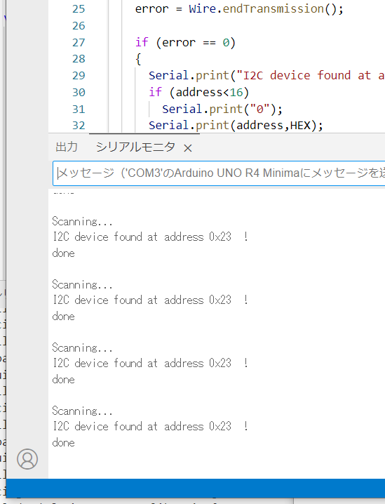
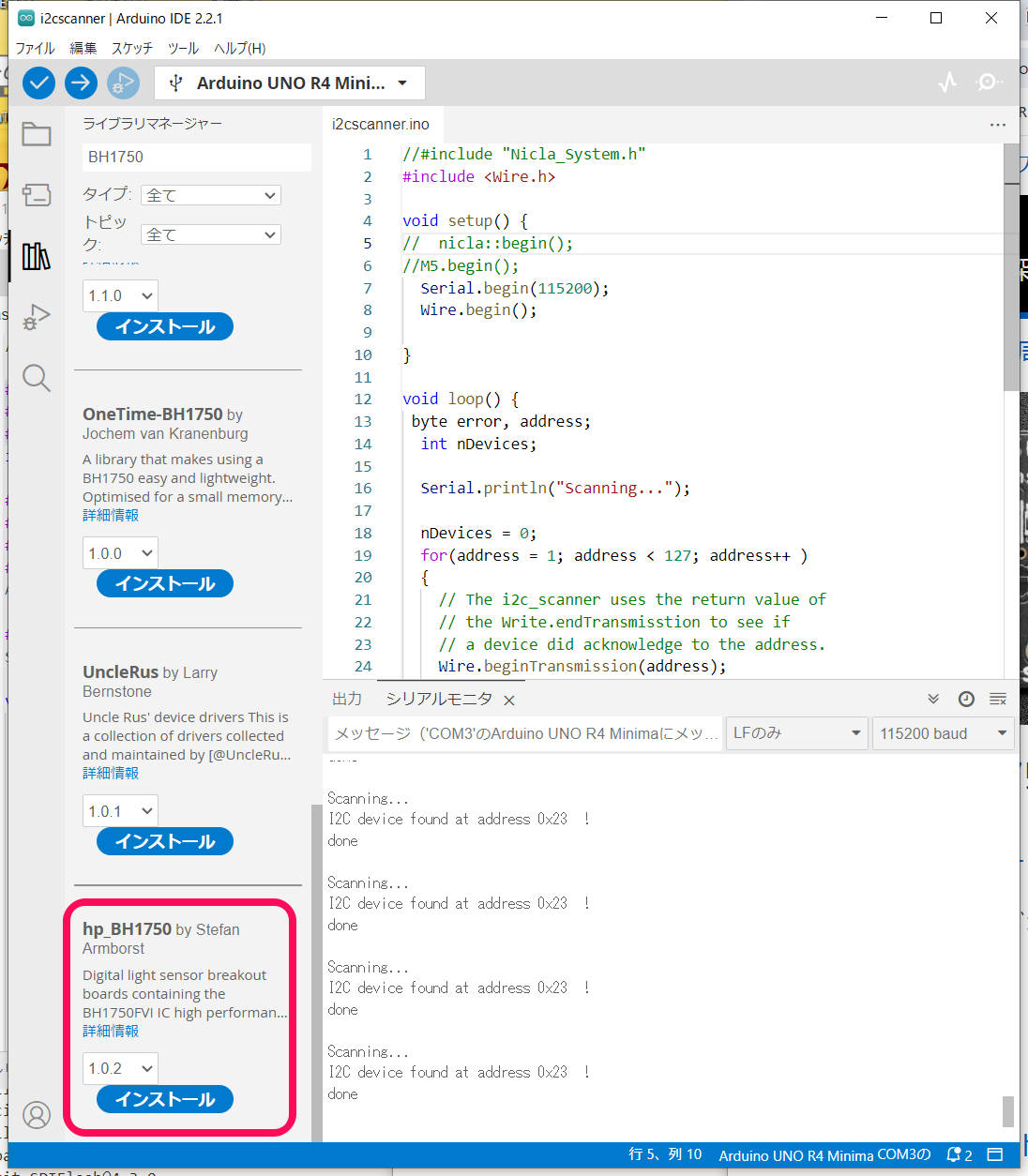
●スレーブ・アドレスを確認
従来からよく使われているi2cScanner.inoを動かしてスレーブ・アドレスを確認します。電源は3.3Vです。
0x23を見つけてきました。
●ライブラリの用意
BH1750で検索して、見つかった hp_BH1750 ライブラリ( Stefan Armborst)をインストールします。
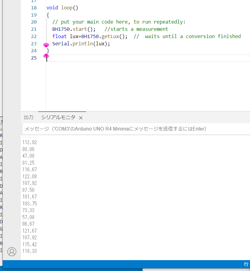
●サンプル・スケッチ
メニューのファイル->スケッチ例から、hp_BH1750 のBareMinimum.inoを選択します。
コンパイル、実行します。ボード上30cmくらいでLEDライトを適当にふっている状態です。単位はlxです。
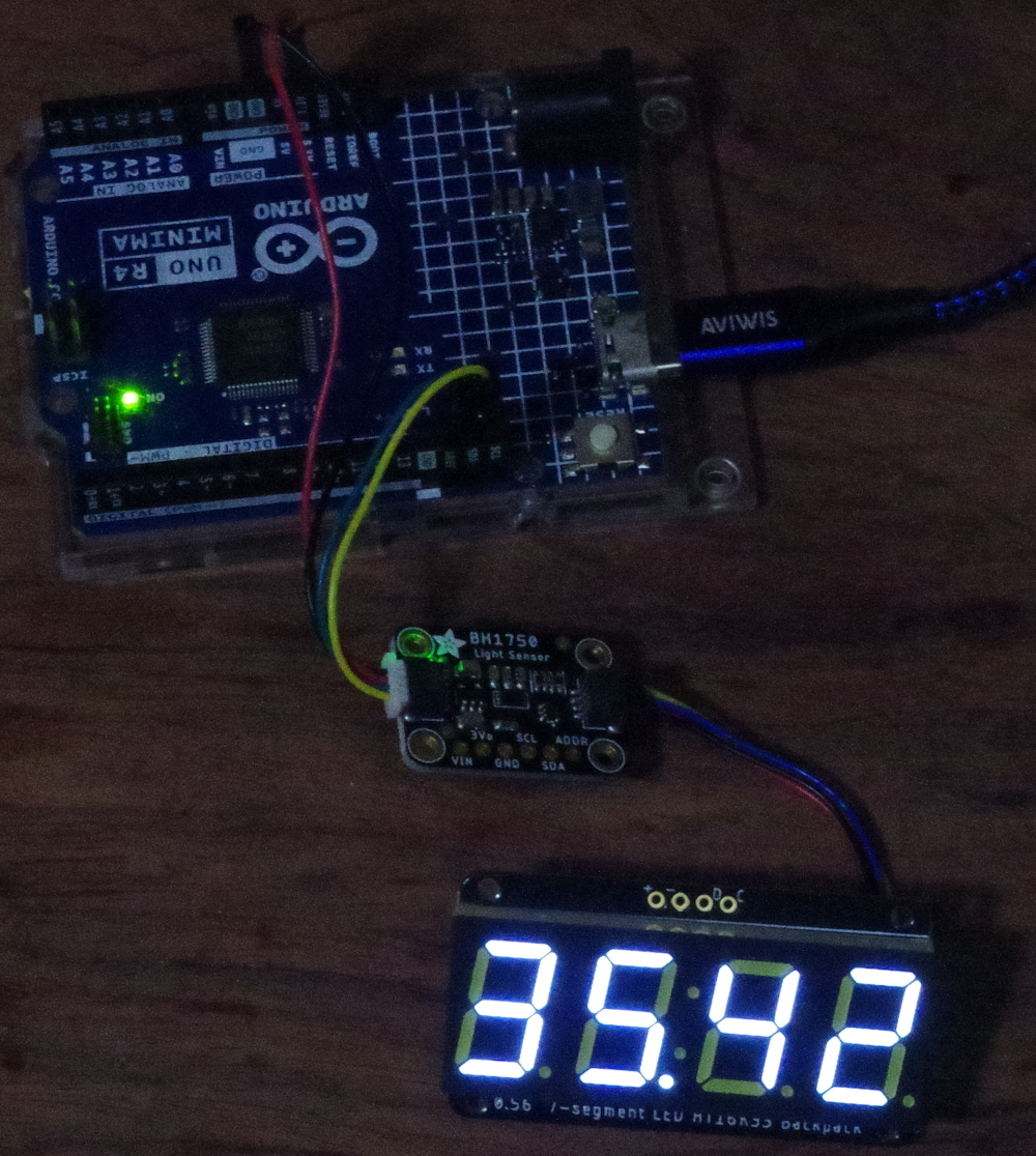
●4桁の7セグメントLED表示器をつないで測定結果を表示する
連載の第4回目の記事を参照しながら表示器を接続します。
Arduino UNO R4 Minimaでセンサ・インターフェーシング ④ 温湿度センサSi7021の測定結果を7セグメントLEDに表示
スケッチです。
7セグメントLED表示器は、第12回 温湿度センサ SHTC3でスレーブ・アドレスが重なったので、デフォルトの0x70から、ジャンパのA0をショートして0x71に変更してあります。デフォルトのまま使うときは0x70で使ってください。
//for help look at: https://github.com/Starmbi/hp_BH1750/wiki
#include <Wire.h>
#include <Adafruit_GFX.h>
#include "Adafruit_LEDBackpack.h"
#include <Arduino.h>
#include <hp_BH1750.h>  //  include the library

Adafruit_7segment matrix = Adafruit_7segment();
hp_BH1750 BH1750;       //  create the sensor

void setup(){
  Serial.begin(9600);
  while (!Serial) { delay(100); }
  bool avail = BH1750.begin(BH1750_TO_GROUND);// init the sensor with address pin connetcted to ground
                                              // result (bool) wil be be "false" if no sensor found
  if (!avail) {
    Serial.println("No BH1750 sensor found!");
    while (true) {};
  }
  matrix.begin(0x71);
  matrix.setBrightness(0x05);  // default 0x0E
}

void loop(){
  // put your main code here, to run repeatedly:
  BH1750.start();   //starts a measurement
  float lux=BH1750.getLux();  //  waits until a conversion finished
  Serial.println(lux);

  matrix.print(lux, DEC);
  matrix.writeDisplay();
  delay(1000);
}
実行例です。
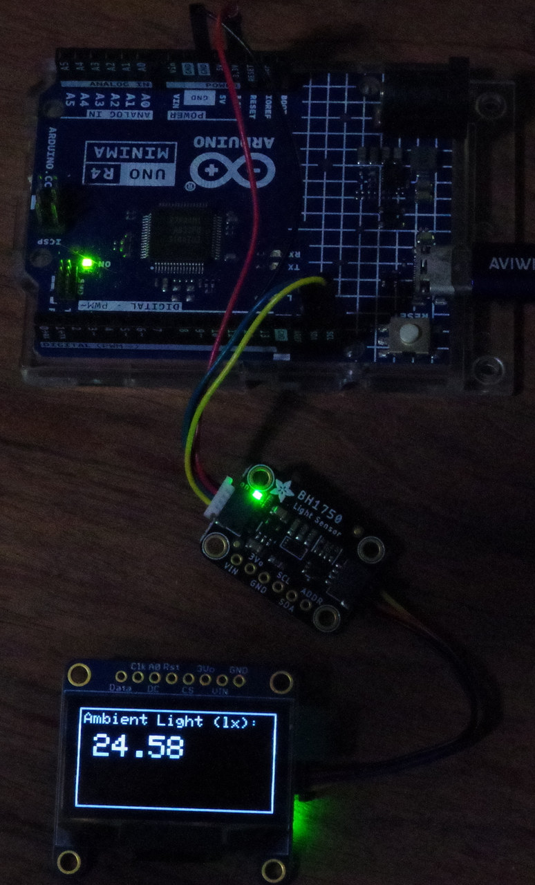
●グラフィック・ディスプレイに測定結果を表示
次の記事を参考に、グラフィック・ディスプレイに測定した明るさを表示します。
Arduino UNO R4 Minimaでセンサ・インターフェーシング ⑤ 温湿度センサSi7021の測定結果をグラフィック・ディスプレイに表示
スケッチです。
//for help look at: https://github.com/Starmbi/hp_BH1750/wiki
#include <Wire.h>
#include <Adafruit_GFX.h>
#include <Adafruit_SSD1306.h>
#include <Arduino.h>
#include <hp_BH1750.h>  //  include the library

#define SCREEN_WIDTH 128 // OLED display width, in pixels
#define SCREEN_HEIGHT 64 // OLED display height, in pixels
#define OLED_RESET    -1 // Reset pin # (or -1 if sharing Arduino reset pin)
#define SCREEN_ADDRESS 0x3D ///< See datasheet for Address; 0x3D for 128x64, 0x3C for 128x32
Adafruit_SSD1306 display(SCREEN_WIDTH, SCREEN_HEIGHT, &Wire, OLED_RESET);

hp_BH1750 BH1750;       //  create the sensor

void setup(){
  Serial.begin(9600);
  while (!Serial) { delay(100); }
  bool avail = BH1750.begin(BH1750_TO_GROUND);// init the sensor with address pin connetcted to ground
                                              // result (bool) wil be be "false" if no sensor found
  if (!avail) {
    Serial.println("No BH1750 sensor found!");
    while (true) {};
  }
  display.begin(SSD1306_SWITCHCAPVCC, SCREEN_ADDRESS);
  display.clearDisplay();
  display.drawRect(0, 0, display.width(), display.height(), SSD1306_WHITE);
  display.setTextSize(1);                // Normal 1:1 pixel scale
  display.setTextColor(SSD1306_WHITE);   // Draw white text
  display.setCursor(3,3);
  display.println("Ambient Light (lx): ");
  display.display();
  delay(200);
}

void loop(){
  // put your main code here, to run repeatedly:
  BH1750.start();   //starts a measurement
  float lux=BH1750.getLux();  //  waits until a conversion finished
  Serial.println(lux);

      display.setTextSize(2);   // Draw 2X-scale text
      display.setTextColor(SSD1306_WHITE);
      display.setCursor(10,17);
      display.fillRect(1, 17, 116, 44, SSD1306_BLACK);
      display.println(lux);
      display.display();
  delay(1000);
}
実行例です。