初めてのArduino ⑤ UNOボードに表示器をつなぐ(その4 fontを修正)
前回、LEDマトリクスで8×8文字構成のフォントを表示しました。数字は間が抜けた感じがします。昔、ドット・プリンタが発売されたころ、ANK文字は5×7の構成でした。その後漢字が印字したいので、16×16から24×24の構成になっていきました。
ここでは、5×8構成の数字を作って表示します。
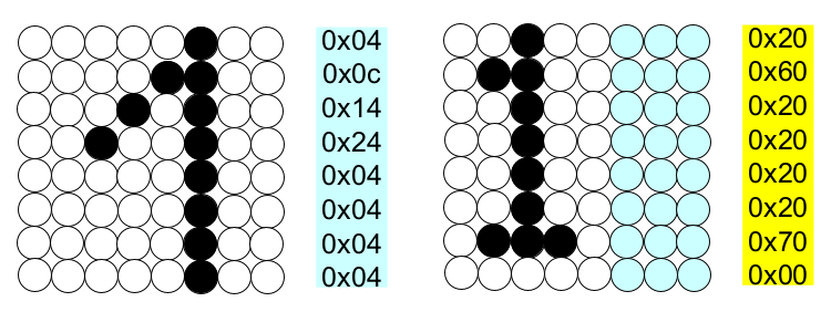
●文字データ
左が前回のデータで、右が新規に作ったデータです。左1列は空けてあります。
●描画ルーチンの修正
drawString()とdrawSprite()で描画していました。drawString()で横8ドットを扱っていたのを5ドットに変更します。drawSprite()は変更なしです。
タブfonts.inoのスケッチです。フォントは数字とドットだけを修正しています。アルファベットは削りました。
// This is the font definition. You can use http://gurgleapps.com/tools/matrix to create your own font or sprites.
// If you like the font feel free to use it. I created it myself and donate it to the public domain.
byte font[95][8] = { {0,0,0,0,0,0,0,0}, // SPACE
                     {0x10,0x18,0x18,0x18,0x18,0x00,0x18,0x18}, // EXCL
                     {0x28,0x28,0x08,0x00,0x00,0x00,0x00,0x00}, // QUOT
                     {0x00,0x0a,0x7f,0x14,0x28,0xfe,0x50,0x00}, // #
                     {0x10,0x38,0x54,0x70,0x1c,0x54,0x38,0x10}, // $
                     {0x00,0x60,0x66,0x08,0x10,0x66,0x06,0x00}, // %
                     {0,0,0,0,0,0,0,0}, // &
                     {0x00,0x10,0x18,0x18,0x08,0x00,0x00,0x00}, // '
                     {0x02,0x04,0x08,0x08,0x08,0x08,0x08,0x04}, // (
                     {0x40,0x20,0x10,0x10,0x10,0x10,0x10,0x20}, // )
                     {0x00,0x10,0x54,0x38,0x10,0x38,0x54,0x10}, // *
                     {0x00,0x08,0x08,0x08,0x7f,0x08,0x08,0x08}, // +
                     {0x00,0x00,0x00,0x00,0x00,0x18,0x18,0x08}, // COMMA
                     {0x00,0x00,0x00,0x00,0x7e,0x00,0x00,0x00}, // -
                     {0x00,0x00,0x00,0x00,0x00,0x00,0x60,0x60}, // DOT
                     {0x00,0x04,0x04,0x08,0x10,0x20,0x40,0x40}, // /
                     {0x30,0x48,0x48,0x48,0x48,0x48,0x30,0x00}, // 0
                     {0x20,0x60,0x20,0x20,0x20,0x20,0x70,0x00}, // 1
                     {0x30,0x48,0x08,0x08,0x30,0x40,0x78,0x00}, // 2
                     {0x30,0x48,0x08,0x30,0x08,0x08,0x70,0x00}, // 3
                     {0x10,0x10,0x30,0x50,0x78,0x10,0x10,0x00}, // 4
                     {0x70,0x40,0x40,0x30,0x08,0x08,0x70,0x00}, // 5
                     {0x30,0x40,0x40,0x70,0x48,0x48,0x30,0x00}, // 6
                     {0x78,0x48,0x10,0x20,0x20,0x20,0x20,0x00}, // 7
                     {0x30,0x48,0x48,0x30,0x48,0x48,0x30,0x00}, // 8
                     {0x30,0x48,0x48,0x38,0x08,0x08,0x30,0x00}, // 9
                      // (the font does not contain any lower case letters. you can add your own.)
                  };    // {}, //

/**
 * This function draws a string of the given length to the given position.
 */
void drawString(char* text, int len, int x, int y ){
  for( int idx = 0; idx < len; idx ++ ){
    int c = text[idx] - 32;

    // stop if char is outside visible area
    if( x + idx * 5  > LEDMATRIX_WIDTH )
      return;

    // only draw if char is visible
    if( 4 + x + idx * 4 > 0 )
      drawSprite( font[c], x + idx * 5, y, 5, 8 );
  }
}

/**
 * This draws a sprite to the given position using the width and height supplied (usually 8x8)
 */
void drawSprite( byte* sprite, int x, int y, int width, int height ){
  // The mask is used to get the column bit from the sprite row
  byte mask = B10000000;

  for( int iy = 0; iy < height; iy++ ){
    for( int ix = 0; ix < width; ix++ ){
      lmd.setPixel(x + ix, y + iy, (bool)(sprite[iy] & mask ));

      // shift the mask by one pixel to the right
      mask = mask >> 1;
    }

    // reset column mask
    mask = B10000000;
  }
}
●メインのタブ
数字がスリムになったので、表示桁を6に増やしました。drawString(Buf, 6, 0, 0);
#include <LEDMatrixDriver.hpp>

int8_t LEDMATRIX_CS_PIN  = 10;
int8_t LEDMATRIX_SEGMENTS = 4;
int8_t LEDMATRIX_WIDTH  =  LEDMATRIX_SEGMENTS * 8;
int8_t sensorPin = A0;
float Vcc = 4.38;
int16_t sensorValue;
float analogSensorData;

LEDMatrixDriver lmd(LEDMATRIX_SEGMENTS, LEDMATRIX_CS_PIN);

void setup() {
  // init the display
  lmd.setEnabled(true);
  lmd.setIntensity(2);   // 0 = low, 10 = high
}

void loop(){
	sensorValue = analogRead(sensorPin);
  analogSensorData = Vcc * sensorValue / 1024.0;

  String sensorValueSTR = String(analogSensorData, DEC);
  char Buf[10]="6.78901";
  sensorValueSTR.toCharArray(Buf, 10);
	drawString(Buf, 6, 0, 0);

	lmd.display();

  delay(1000);
}
●A-Dコンバータ
A-Dコンバータは、アナログ入力をディジタル・データに変換する際、基準電圧と比較をします。今回、何も設定しないと電源電圧が基準電圧になります。LEDマトリクスの消費電流が多いのと、点灯するLEDの数が変化するので、電流が大きく変わり、電源電圧は変動します。5VはUSBケーブルからの電圧です。
したがって、表示される電圧はふらふらと変化します。
Arduino UNOで使われているマイコンのA-Dコンバータは、外部基準電圧、内部基準電圧の2通りが選択できます。
Arduino UNOボード上では、外部電源もしくはUSB電源から3端子レギュレータを通して3.3Vの電圧を作っています。そこそこ安定です。
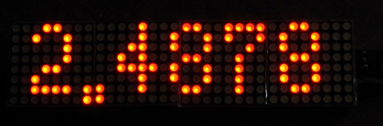
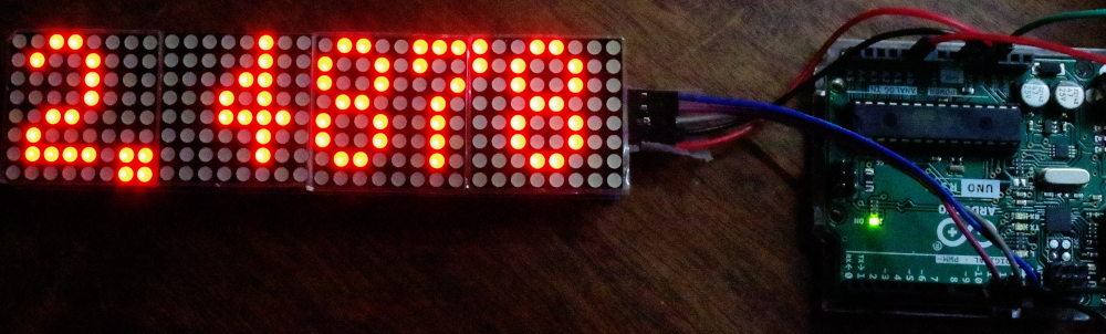
そこで、3.3V端子をAREFにつなぎます。A0端子には2.48Vの実験用電源の出力をつなぎます。ボード上の3.3Vを測ると3.30Vでした。
メインのスケッチです。setup()内で、analogReference(EXTERNAL);とAREF端子につながっている外部電源を使うように指示します。アナログ入力端子に入力できる電圧は、0~3.3Vになります。
#include <LEDMatrixDriver.hpp>

int8_t LEDMATRIX_CS_PIN  = 10;
int8_t LEDMATRIX_SEGMENTS = 4;
int8_t LEDMATRIX_WIDTH  =  LEDMATRIX_SEGMENTS * 8;
int8_t sensorPin = A0;
float Vcc = 3.3;
int16_t sensorValue;
float analogSensorData;

LEDMatrixDriver lmd(LEDMATRIX_SEGMENTS, LEDMATRIX_CS_PIN);

void setup() {
  // init the display
  lmd.setEnabled(true);
  lmd.setIntensity(2);   // 0 = low, 10 = high
  analogReference(EXTERNAL);
}

void loop(){
	sensorValue = analogRead(sensorPin);
  analogSensorData = Vcc * sensorValue / 1024.0;

  String sensorValueSTR = String(analogSensorData, DEC);
  char Buf[10]="6.78901";
  sensorValueSTR.toCharArray(Buf, 10);
	drawString(Buf, 6, 0, 0);

	lmd.display();

  delay(1000);
}
表示はぴたっと止まっています。時々最後の2桁が変化します。
基準電圧が3.30Vなので、1LSBは3.22mVです。2.4878Vで1LSB増えると計算上2.4910Vになります。じっと観察していると2.4911Vの表示になることがあります。
●ドットの前後を詰める
小数点のある数値があまりかっこよくないです。ドットが間延びして表示されるからです。小数点が出てくるまでは右に、小数点が出た後は左に少し詰めるようにスケッチを変更しました。修正したのはdrawString()関数だけです。
void drawString(char* text, int len, int x, int y ){
  Serial.println("---");
  int flag=0;
  for( int idx = 0; idx < len; idx ++ ){
    int c = text[idx] - 32;

    // stop if char is outside visible area
    if( x + idx * 5  > LEDMATRIX_WIDTH )
      return;

    // only draw if char is visible
    if( 4 + x + idx * 4 > 0 )
      if (!flag)
        drawSprite( font[c], x+1 + idx * 5, y, 5, 8 );
      else  {
        drawSprite( font[c], x-1 + idx * 5, y, 5, 8 );
        flag = 1;}

      if (c==14) flag = 1;
  }
}