MOSFETとマイコン (4) DCモータを動かす その2
■Bluetoothの通信もできる
前回、Micro:bitでDCモータを制御できました。このモータを離れたところからコントロールします。
Micro:bitにはBluetoothが搭載されています。逆ですね、BluetoothのコントローラにCortex-M0が使われているので、Arduinoとして利用しているのが本当の姿です。コントロールには、スマホを利用します。
●Bluetoothのライブラリをインストール
BluetoothのライブラリをMicro:bitにインストールします。arduino-BLEPeripheralのGitHubに行って、zipファイルをダウンロードします。
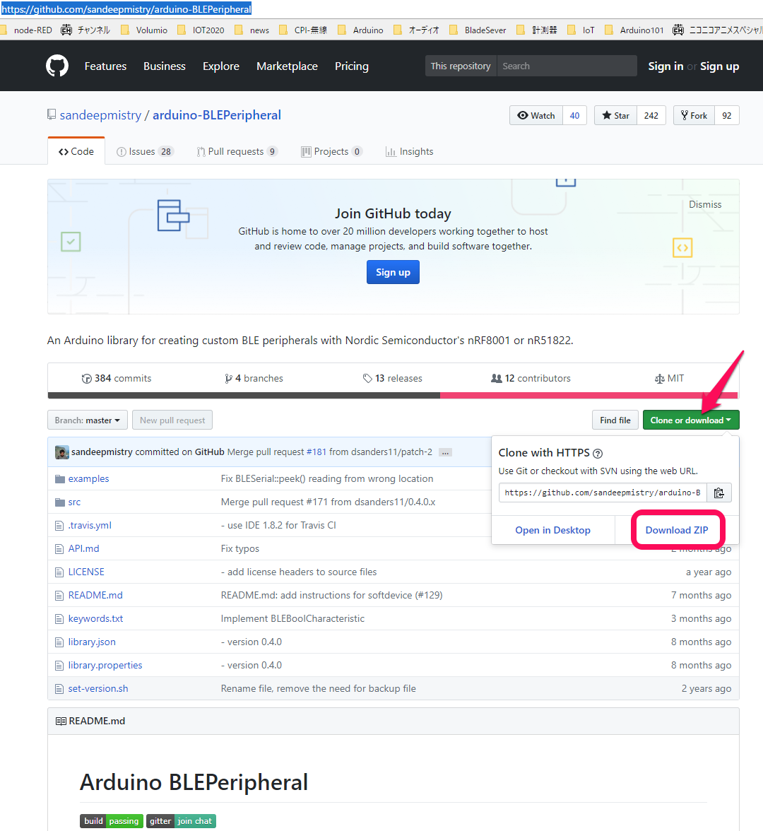
Micro:bitのArduino IDEで、ダウンロードしたライブラリを組み込みます。
| メニューのスケッチ->ライブラリをインクルード-> .ZIP形式のライブラリをインクルード |
開いたエクスプローラで、ダウンロード・フォルダにある「arduino-BLEPeripheral-master.zip」を選択すると、ライブラリやサンプルが組み込まれます。通常のライブラリであれば、これで使えるようになるのですが、Bluetoothを使うには、もう一つ作業をします。
上記のGitHubのページの中ごろに、arduino-nRF5x core usersという見出しがあります。その見出しの次にSoftDeviceを組み込むようにと説明があります。
| The arduino-nRF5x core REQUIRES a SoftDevice in order to successfully use this library. Please see Flashing a SoftDevice. |
上記の文章にある「Flashing a SoftDevice」のリンクをクリックします。arduino-nRF5のGitHubのページの途中にある「Flashing a SoftDevice」見出しに飛びます。ここに書かれているうち、項目2番目から実行します。
② \ドキュメント\Arduinoの下に、tools\nRF5FlashSoftDevice\tool\をつくる。
③ \ドキュメント\Arduino\tools\nRF5FlashSoftDevice\tool\のなかに、nRF5FlashSoftDevice.jar をダウンロードして保存する。
④ Arduino IDEをいったん終了し、再度起動する。
メニューのツールから、
⑤ ボードがBBC micro:bitになっていることを確認する。
⑥ SoftDevice:がS110になっていることを確認する。
⑦ 書き込み装置をCMSIS-DAPにする。
⑧ ツールからnRF5 Flash SoftDeviceを選ぶ。Acceptをクリックする。
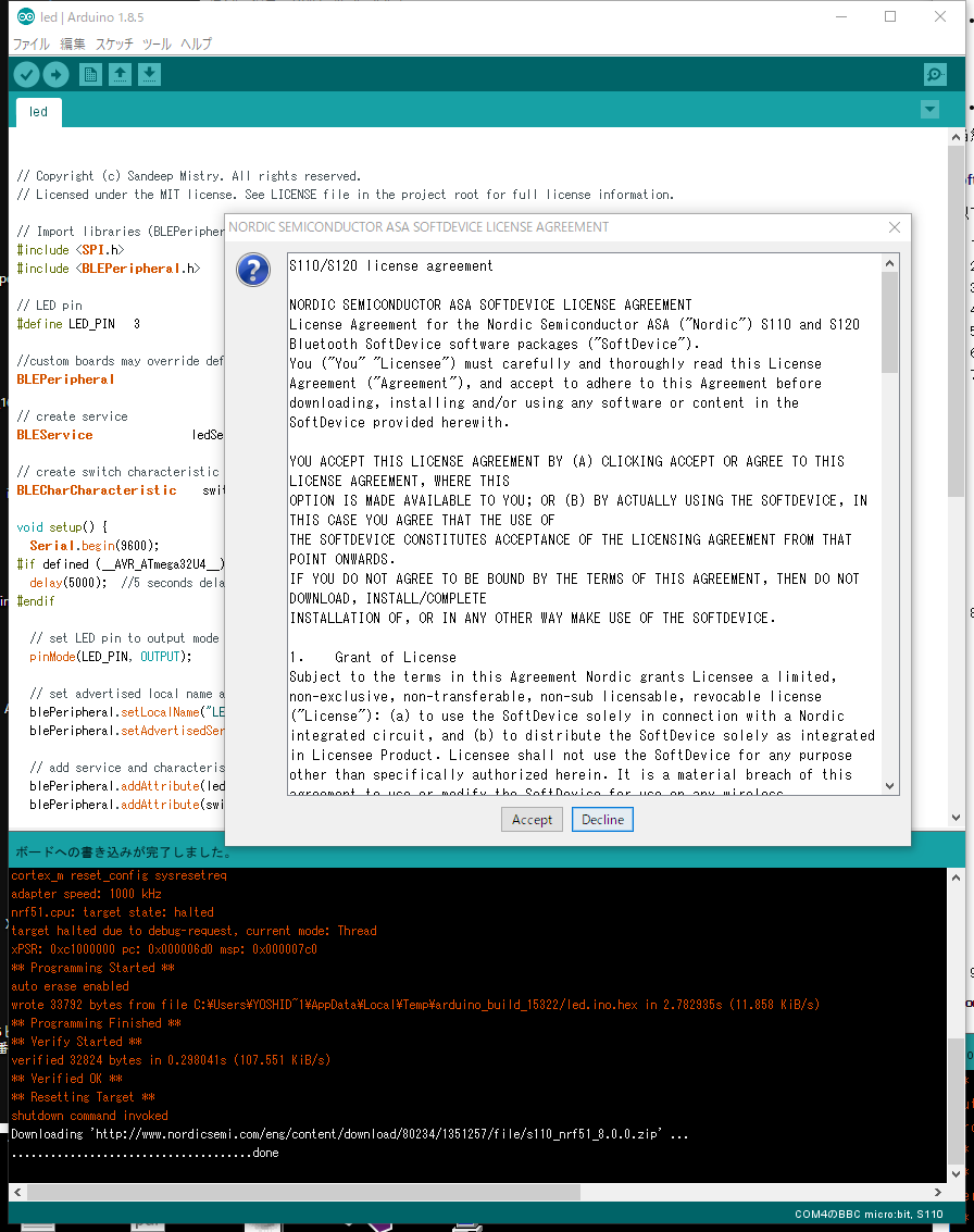
スケッチ例のBLEPeripheral->LEDを選び、Micro:bitに書き込みます。
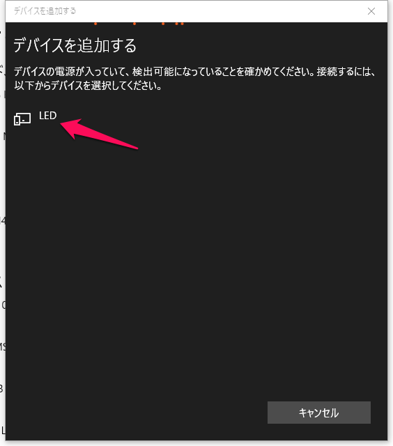
たとえば、BluetoothをサポートするWindows PCの「設定」->「デバイス」 ->「Bluetoothとその他のデバイス」->「Bluetoothとその他のデバイスを追加する」->「Bluetooth」からLEDを見つけてきます。LEDが見つかると、ライブラリのインストールが正しく行えていることが確認できます。
●動作確認
動作確認は、iOSもしくはAndroidのアプリnRF Connect を使います(二つは少しメニューなどが異なる)。その前に、サンプル・スケッチのLEDに2行追加します。
// set LED pin to output mode
 pinMode(LED_PIN, OUTPUT);
 pinMode(26, OUTPUT); // add
 digitalWrite(26, HIGH); // add
マイコンへスケッチを書き込むと、5×5マトリクスの左上のLEDが点灯します。左上のアドレスは、ROW=3、COL=26です。26番をHIGHにし、3番をLOWにするとLEDが点灯します。デフォルトがLOWなので、点灯しています。
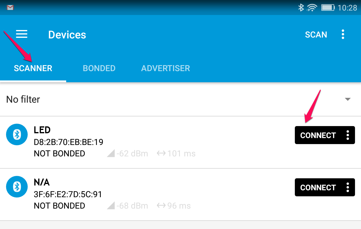
SCANNER をタップして開始し、LEDが検知されたら、[CONNECT] ボタンをタップします。
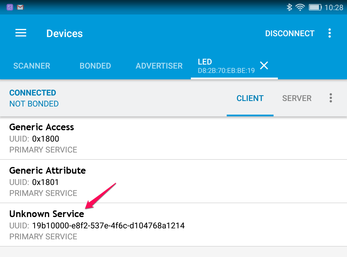
Unkown Serviceをタップします。
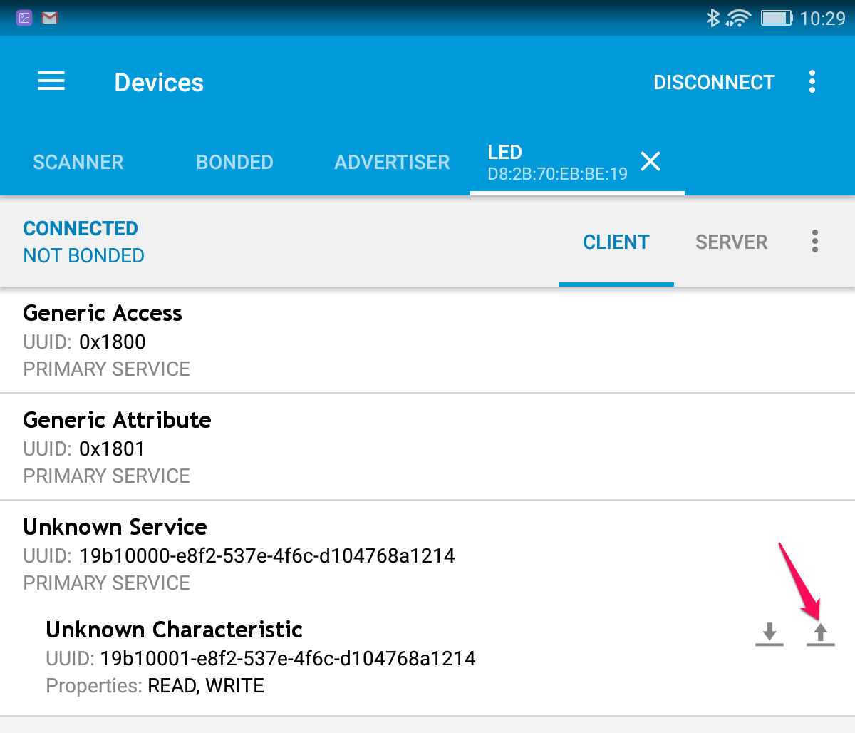
画面右にある上向きの矢印をタップします。検出エリアが狭いのか、何度も押さないと入力パネルが出ません。
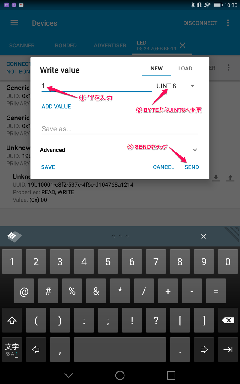
単位をUINT 8に変更した後、Write valueに'1'を入力し、SENDで送信します。iPadでは単位は出てきません。

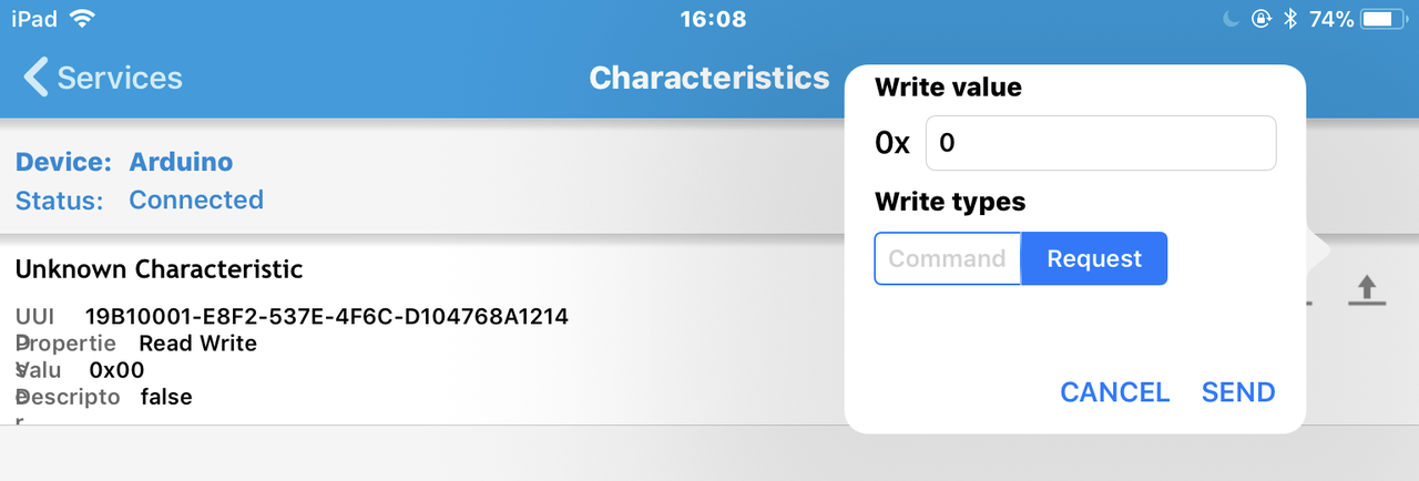
1を送ると左上のLEDは消灯し、0を送ると左上のLEDは点灯します。これで、Bluetoothの通信ができました。スマホがセントラル(マスタ、サーバ)で、Micro:bitがペリフェラル(スレーブ、クライアント)です。Bluetoothではセントラルとペリフェラルはどちらでもなりえますが、ここで用いたarduino-BLEPeripheralライブラリは、ペリフェラル用です。
●モータをコントロール
Micro:bitのLEDをリモートからON/OFFできたので、モータを動かすようにスケッチを修正します。
下記のスケッチを書き込んでからnRF Connectを起動すると、LEDではなくMotorが見つかります。入力数値は1がCW、2がCCW、1もしくは2を入れて回転している状態で、3が高速回転、4が低速回転です。それ以外の数値を入れるとストップします。
#include <SPI.h>
#include <BLEPeripheral.h>
// LED pin
#define LED_PIN 3
// Motor pin
#define IN1 7
#define IN2 6
#define PWM 5
//custom boards may override default pin definitions with BLEPeripheral(PIN_REQ, PIN_RDY, PIN_RST)
BLEPeripheral blePeripheral = BLEPeripheral();
// create service
BLEService ledService = BLEService("19b10000e8f2537e4f6cd104768a1214");
// create switch characteristic
BLECharCharacteristic switchCharacteristic = BLECharCharacteristic("19b10001e8f2537e4f6cd104768a1214", BLERead | BLEWrite);

void setup() {
    Serial.begin(9600);
// set LED pin to output mode
    pinMode(LED_PIN, OUTPUT);
    pinMode(26, OUTPUT);
    digitalWrite(26, HIGH);

    pinMode(IN1,OUTPUT);
    pinMode(IN2,OUTPUT);
    pinMode(PWM,OUTPUT);

    digitalWrite(IN1,LOW);
    digitalWrite(IN2,LOW);
    digitalWrite(PWM,HIGH);//Stop Mode
 // ---GATT start
 // set advertised local name and service UUID
    blePeripheral.setLocalName("Motor");
    blePeripheral.setAdvertisedServiceUuid(ledService.uuid());
// add service and characteristic
    blePeripheral.addAttribute(ledService);
    blePeripheral.addAttribute(switchCharacteristic); // GATT end
// begin initialization
    blePeripheral.begin();
    Serial.println(F("BLE Motor Peripheral"));
}

void loop() {
    BLECentral central = blePeripheral.central();
    if (central) {
// central connected to peripheral
        Serial.print(F("Connected to central: "));
        Serial.println(central.address());
        analogWrite(PWM, 100);

        while (central.connected()) {
              switch (switchCharacteristic.value()) {
              case 1:
                  Serial.println(F("Motor CCW"));
                  digitalWrite(LED_PIN, HIGH);
                  digitalWrite(IN1,LOW);digitalWrite(IN2,HIGH);
                  break;
              case 2:
                  Serial.println(F("Motor CW"));
                  digitalWrite(LED_PIN, LOW);
                  digitalWrite(IN1,HIGH);digitalWrite(IN2,LOW);
                  break;
              case 3:
                  analogWrite(PWM, 150);
                  Serial.println(F("Motor fast"));
                  break;
              case 4:
                  analogWrite(PWM, 50);
                  Serial.println(F("Motor slow"));
                  break;
              default:
                  Serial.println(F("Motor STOP"));
                  digitalWrite(LED_PIN, LOW);
                  digitalWrite(IN1,LOW);digitalWrite(IN2,LOW);digitalWrite(PWM,HIGH);
              }
          }

// central disconnected
    Serial.print(F("Disconnected from central: "));
    Serial.println(central.address());
    }
}
// Copyright (c) 2016 Intel Corporation. All rights reserved.
// Copyright (c) Sandeep Mistry. All rights reserved.
// Licensed under the MIT license. See LICENSE file in the project root for full license information.
●次のステップ 保留
スマホから、Bluetoothを使ってMicro:bitにつないだDCモータをコントロールできました。使い勝手がよくないので、専用のプログラムを作ると便利です。
- スマホで専用のプログラムを作る
- もう1台Micro:bitを用意し、DCモータ側をセントラル、操作側をペリフェラルにしてコントロールする
Arduino IDEでは、どちらもプログラミングできません。Micro:bitのGUIによるプログラミングでは可能と思われます。Arduino IDE用BLEセントラルのライブラリが利用できるようになったら、続きをしたいと思います。
※参考URL https://www.arduino.cc/en/Guide/Arduino101
https://developer.apple.com/jp/documentation/CoreBluetoothPG.pdf