ラズパイ5 pythonの仮想環境 ⑩ 12ビットA-DコンバータADS1015<その3>pythonでグラフィック・ディスプレイを利用
4ポートの入力電圧を、グラフィック・ディスプレイに表示します。
利用したグラフィック。ディスプレイと接続は、次の記事を参照してください。
ラズパイ2023年10月更新 bookworm ③ pipが使えない! pythonでグラフィック・ディスプレイを利用
●仮想環境にst7789をインストール
前回作ったenvadcの仮想環境に入ります。
yoshi@ras05:~ $ source envadc/bin/activate
(envadc) yoshi@ras05:~ $ pip list
Package Version
---------- -------
i2cdevice 1.0.0
pip 23.0.1
setuptools 66.1.1
smbus2 0.4.3
st7789ライブラリをインストールします。
(envadc) yoshi@ras05:~ $ pip install st7789
Looking in indexes: https://pypi.org/simple, https://www.piwheels.org/simple
Collecting st7789
Using cached https://www.piwheels.org/simple/st7789/ST7789-0.0.4-py3-none-any.whl (8.4 kB)
Installing collected packages: st7789
Successfully installed st7789-0.0.4
実行に必要な、pillow、numpy、spidevをインストールしました。
(envadc) yoshi@ras05:~ $ pip list
Package Version
---------- -------
i2cdevice 1.0.0
numpy 1.26.4
pillow 10.2.0
pip 23.0.1
setuptools 66.1.1
smbus2 0.4.3
spidev 3.6
ST7789 0.0.4
このst7789ライブラリでは、GPIOの制御にRPi.GPIOライブラリが使われていますが、ラズパイ5では動きません。代替ライブラリであるgpiozeroは、仮想環境で動きません。GPIOをON/OFFするシェル・コマンドのecho 21 > /sys/class/gpio/exportはラズパイ5ではうごかなくなりました。いずれも執筆時点の状況です。
pinctrl は新しいです。raspberrypi/utilsのなかでは、次のように紹介されています。
| pinctrl - raspi-gpio のより強力な代替品。カーネルをバイパスして、システムの GPIO とピンの多重化状態を表示および変更するためのツールです。 |
インストールしたst7789ライブラリ内の__init__.pyのなかで、GPIOを操作しているRPi.GPIOの処理部分をpinctrl で書き換えます。
pinctrl は、入出力のモード変更と同時に、High/Lowの変更を同時に制御できます。helpに、具体的な指定方法が出ています。
pinctrl set 20 op pn dh Set GPIO20 to output with no pull and driving high
GPIO21-GND間にLEDをつなぎ、次のコマンドを実行します。LEDが点灯、消灯します。opが出力の設定、dh/dlがHigh/Lowの変更です。
$ pinctrl set 21 op dh
$ pinctrl set 21 op dl
プログラムの中では、シェル・コマンドとして実行させます。
msg = 'pinctrl set 21 op dh'
subprocess.run(msg,shell=True)
/home/yoshi/envadc/lib/python3.11/site-packages/ST7789のなかにある__init__.pyを書き換えました。
backlight信号の制御はもともと配線されていないので、全部コメントアウトしました。
rst信号は、reset()で使われています。pinctrl set 25 op dhとpinctrl set 25 op dlに置き換えました。
dc信号は、send()で使われています。 # Set DC low for command, high for data.と書かれていてGPIO.output(self._dc, is_data)の部分をpinctrlで同様のON/OFFするように書き換えました。
|
# Copyright (c) 2014 Adafruit Industries import spidev import subprocess __version__ = '0.0.4' BG_SPI_CS_BACK = 0 SPI_CLOCK_HZ = 16000000 ST7789_NOP = 0x00 ST7789_SLPIN = 0x10 ST7789_INVOFF = 0x20 ST7789_CASET = 0x2A ST7789_PTLAR = 0x30 ST7789_FRMCTR1 = 0xB1 ST7789_GCTRL = 0xB7 ST7789_LCMCTRL = 0xC0 ST7789_RDID1 = 0xDA ST7789_GMCTRP1 = 0xE0 ST7789_PWCTR6 = 0xFC
def __init__(self, port, cs, dc, backlight=None, rst=None, width=240, Must provide the GPIO pin number for the D/C pin and the SPI driver. Can optionally provide the GPIO pin number for the reset pin as the rst parameter. :param port: SPI port number """ if width != height and rotation in [90, 270]: # GPIO.setwarnings(False) self._spi = spidev.SpiDev(port, cs) self._dc = dc self._offset_left = offset_left # Set DC as output. # Setup backlight as output (if provided). # Setup reset as output (if provided). self.reset() def send(self, data, is_data=True, chunk_size=4096): # Convert scalar argument to list so either can be passed as parameter. def set_backlight(self, value): @property @property def command(self, data): def data(self, data): def reset(self): def _init(self): self.command(ST7789_SWRESET) # Software reset self.command(ST7789_MADCTL) self.command(ST7789_FRMCTR2) # Frame rate ctrl - idle mode self.command(ST7789_COLMOD) self.command(ST7789_GCTRL) self.command(ST7789_VCOMS) self.command(ST7789_LCMCTRL) # Power control self.command(ST7789_VDVVRHEN) # Power control self.command(ST7789_VRHS) # Power control self.command(ST7789_VDVS) # Power control self.command(0xD0) self.command(ST7789_FRCTRL2) self.command(ST7789_GMCTRP1) # Set Gamma self.command(ST7789_GMCTRN1) # Set Gamma if self._invert: self.command(ST7789_SLPOUT) self.command(ST7789_DISPON) # Display on def begin(self): Deprecated. Included in __init__. """ def set_window(self, x0=0, y0=0, x1=None, y1=None): if y1 is None: y0 += self._offset_top x0 += self._offset_left self.command(ST7789_CASET) # Column addr set def display(self, image): :param image: Should be RGB format and the same dimensions as the display hardware. """ # Convert image to 16bit RGB565 format and # Write data to hardware. def image_to_data(self, image, rotation=0): # Rotate the image # Mask and shift the 888 RGB into 565 RGB # Stick 'em together # Output the raw bytes |
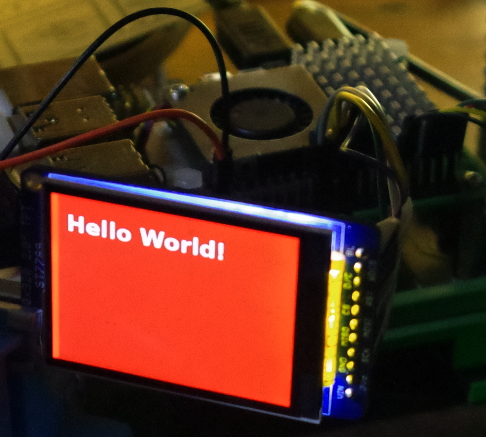
描画テスト用のst7789a.pyです。
|
from PIL import Image import ST7789 MESSAGE = "Hello World!" #display_type == "dhmini":
WIDTH = disp.width draw = ImageDraw.Draw(img) font = ImageFont.truetype("/usr/share/fonts/truetype/dejavu/DejaVuSans-Bold.ttf", 30) draw.text((20,20),MESSAGE, font=font, fill=(255,255,255)) disp.display(img) |
実行結果です。
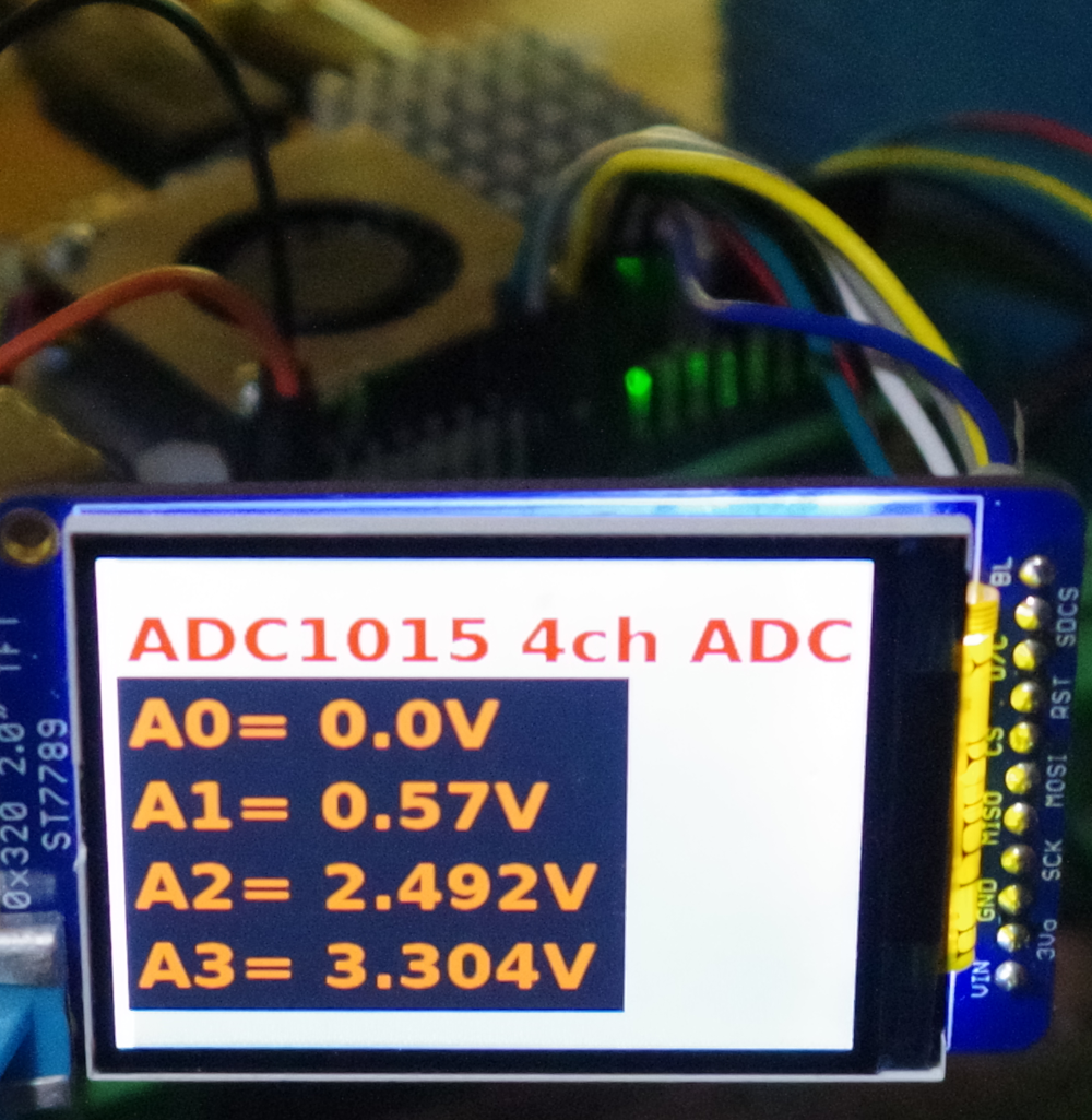
●A-Dコンバータの出力を表示
プログラムです。ADC1015のデータ読み取りは、smbus2を使った方法です。
|
from PIL import Image addr = 0x48 bus = SMBus(1) def sign16(x): def readVoltage(): MESSAGE = "ADC1015 4ch ADC" disp = ST7789.ST7789( height=240,width=320,rotation=0, while 1: print('\nA0={:.3f}V A1={:.3f}V A2={:.3f}V A3={:.3f}V '.format(voltageA0,voltageA1,voltageA2,voltageA3)) |
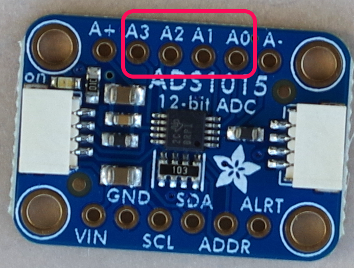
実行中の様子です。A0はGNDへ、A1は解放、A2はTL431電源へ、A3はVin端子につないでいます。