初心者のためのLTspice 入門 シミュレーション結果を保存しその結果を利用する(3)BVコンポーネントでいろいろな信号を作る
●LTspiceでランダム・ノイズ(ホワイト・ノイズ)を作成
voltageを利用すると、プラス・マイナスの電源の供給以外に、シミュレーションの入力信号として正弦波、パルス、PWLによる任意の信号源となります。このほかにLTspiceでは、BVコンポーネントを利用すると、関数の組み合わせでより多様な出力を合成できます。最初に正弦波を作成します。
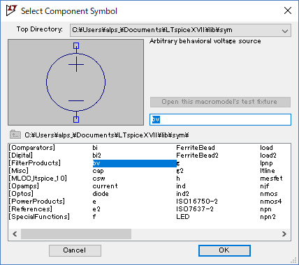
●BV(Arbitrary behavioral voltage source)のコンポーネント
BVのコンポーネントは電圧源のVと同じ形のシンボルですが、その扱いはまったく異なります。回路図にこのBVをドラッグしてセットします。
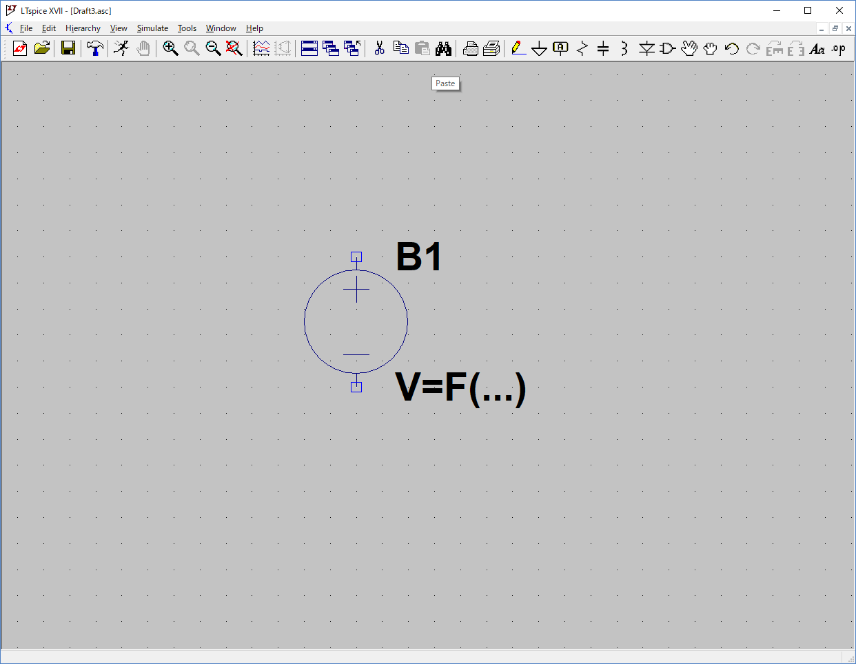
BVのデバイスを回路図に設定すると次に示すように、電圧の欄には、電圧の変化を示す式を記入します。
| V = F(…) |
この F(…) の部分に、関数を含んだ式を設定します。
この式に利用できる関数と演算子は、LTspiceのHelpのトピックスでCircuit ElementのB. Arbitrary Behavioral Voltage or Current Sourcesを選択すると表示される、次の表に記載されています。
| Function Name | Description |
| abs(x) | Absolute value of x |
| absdelay(x,t[,tmax]) | x delayed by t. Optional max delay notification tmax. |
| acos(x) | Real part of the arc cosine of x, e.g., acos(-5) returns 3.14159, not 3.14159+2.29243i |
| arccos(x) | Synonym for acos() |
| acosh(x) | Real part of the arc hyperbolic cosine of x, e.g., acosh(.5) returns 0, not 1.0472i |
| asin(x) | Real part of the arc sine of x, asin(-5) is -1.57080, not -1.57080+2.29243i |
| arcsin(x) | Synonym for asin() |
| asinh(x) | Arc hyperbolic sine |
| atan(x) | Arc tangent of x |
| arctan(x) | Synonym for atan() |
| atan2(y,x) | Four quadrant arc tangent of y/x |
| atanh(x) | Arc hyperbolic tangent |
| buf(x) | 1 if x > .5, else 0 |
| ceil(x) | Integer equal or greater than x |
| cos(x) | Cosine of x |
| cosh(x) | Hyperbolic cosine of x |
| ddt(x) | Time derivative of x |
| delay(x,t[,tmax] | Same as absdelay() |
| dnlim(x,y,z) | Similar to max(x,y) but with a continuous 1st derivative transition width z |
| exp(x) | e to the x |
| floor(x) | Integer equal to or less than x |
| hypot(x,y) | sqrt(x**2 + y**2) |
| idt(x[,ic[,a]]) | Integrate x, optional initial condition ic, reset if a is true. |
| idtmod(x[,ic[,m[,o]]] | Integrate x, optional initial condition ic, reset on reaching modulus m, offset output by o. |
| if(x,y,z) | If x > .5, then y else z |
| int(x) | Convert x to integer |
| inv(x) | 0. if x > .5, else 1. |
| limit(x,y,z) | Intermediate value of x, y, and z |
| ln(x) | Natural logarithm of x |
| log(x) | Alternate syntax for ln() |
| log10(x) | Base 10 logarithm |
| max(x,y) | The greater of x or y |
| min(x,y) | The smaller of x or y |
| pow(x,y) | Real part of x**y, e.g., pow(-1,.5)=0, not i. |
| pwr(x,y) | abs(x)**y |
| pwrs(x,y) | sgn(x)*abs(x)**y |
| rand(x) | Random number between 0 and 1 depending on the integer value of x. |
| random(x) | Similar to rand(), but smoothly transitions between values. |
| round(x) | Nearest integer to x |
| sdt(x[,ic[,assert]]) | Alternate syntax for idt() |
| sgn(x) | Sign of x |
| sin(x) | Sine of x |
| sinh(x) | Hyperbolic sine of x |
| sqrt(x) | Square root of x |
| table(x,a,b,c,d,...) | Interpolate a value for x based on a look up table given as a set of pairs of points. |
| tan(x) | Tangent of x. |
| tanh(x) | Hyperbolic tangent of x |
| u(x) | Unit step, i.e., 1 if x > 0., else 0. |
| uplim(x,y,z) | Similar to min(x,y) but with a continuous 1st derivative transition width z |
| uramp(x) | x if x > 0., else 0. |
| white(x) | Random number between -.5 and .5 smoothly transitions between values even more smoothly than random(). |
| !(x) | Alternative syntax for inv(x) |
| ~(x) | Alternative syntax for inv(x) |
- The following operations, grouped in reverse order of precedence of evaluation:
| Operand | Description |
| & | Convert the expressions to either side to Boolean, then AND. |
| | | Convert the expressions to either side to Boolean, then OR. |
| ^ | Convert the expressions to either side to Boolean, then XOR. |
| > | True if expression on the left is greater than the expression on the right, otherwise false. |
| < | True if expression on the left is less than the expression on the right, otherwise false. |
| >= | True if expression on the left is greater than or equal the expression on the right, otherwise false. |
| <= | True if expression on the left is less than or equal the expression on the right, otherwise false. |
| + | Floating point addition |
| - | Floating point subtraction |
| * | Floating point multiplication |
| / | Floating point division |
| ** | Raise left hand side to power of right hand side. Only the real part is returned, e.g., -1**1.5 gives zero not i. |
| ! | Convert the following expression to Boolean and invert. |
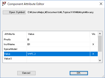
●BVの設定
BVの設定は、回路図BVのデバイスをマウスの右ボタンでクリックすると、次に示す「Component Attribute Editor」が表示されます。この中のValueの欄に設定する式を入力します。
BV(Arbitrary behavioral voltage)は、出力の47種類にも及ぶ各種の関数とほかのノードの出力電圧や複数のノードの出力電圧の差、およびそれらの関数、ノードの出力の演算結果を設定できます。
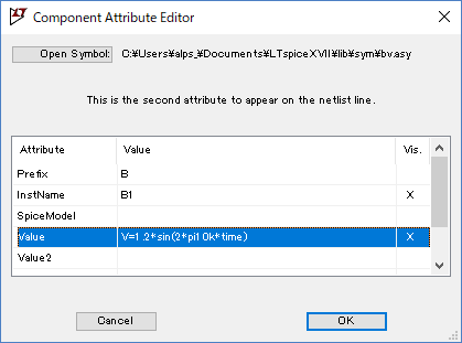
今回設定は正弦波を出力します。sin()関数を使用し経過時間はtimeを使用します。
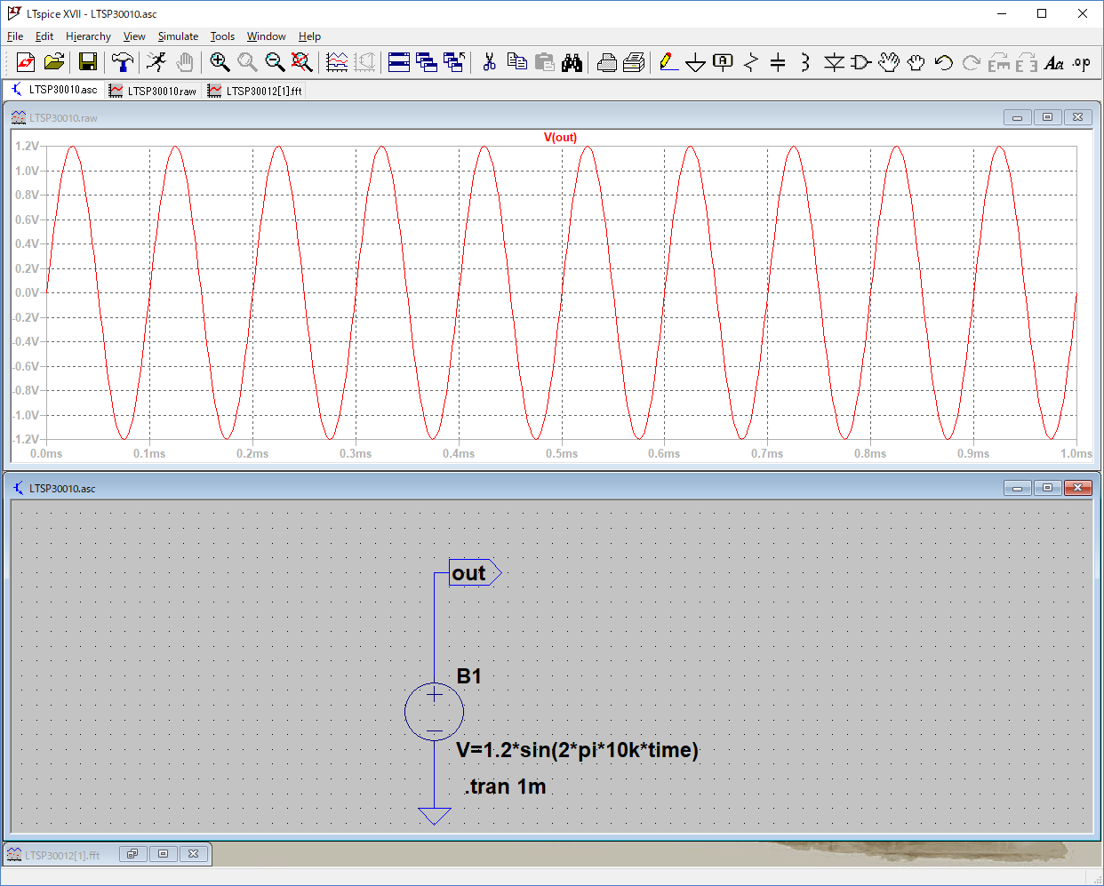
円周率の π の値は定数 pi で示すことができます。sin(2*pi*time)で1Hzの正弦波となります。10kHzの出力となるようにするのでsin(2*pi*10k*time)と関数を設定します。次のようにValueの値を入力します。timeはシミュレーション時間で単位が秒で、timeの係数が正弦波の周波数となります。ここでは、10kがその値で10kHzの正弦波が出力されます。
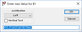
回路図のBVの V=F(…) の部分をマウスの右ボタンでクリックすると、次に示すBVのValueの入力画面になります。この画面でValueの値を設定、再設定できます。
●シミュレーション結果
次に、BVの出力をシミュレーションしました。1波長の周期は0.1msで指定した10kHzの周波数になっています。サイン関数の1周期は2πですから、秒の単位の時間の係数10kが周波数となります。
波形の大きさは、先頭の係数1.2にsin関数が1から-1の間を変動するので、シミュレーション結果の正弦波は+1.2Vから-1.2Vの範囲となります。
●white関数
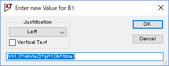
この関数は、0.5から-0.5の間のランダムな数値が得られます。各値の間はスムーズにつながります。乱数値を発生させる関数はこのほかに、一般的な0と1の間の乱数を発生するrand(x)、発生する値の遷移が滑らかになるrandom(x)があります。white関数はrandom(x)とは発生する値の遷移がよりスムーズで、-0.5と+0.5の範囲の値が出力されます。ここではsin関数をwhite関数に次のように変更しました。
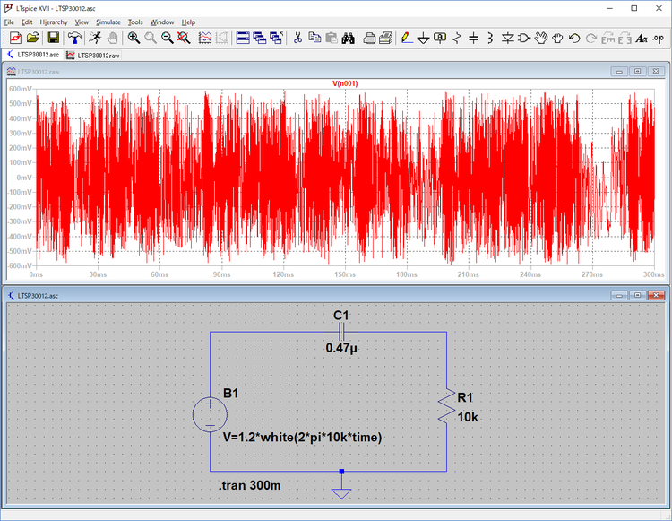
シミュレーションの結果は次のようになり、簡単にランダム・ノイズ(ホワイト・ノイズ)を作成できます。
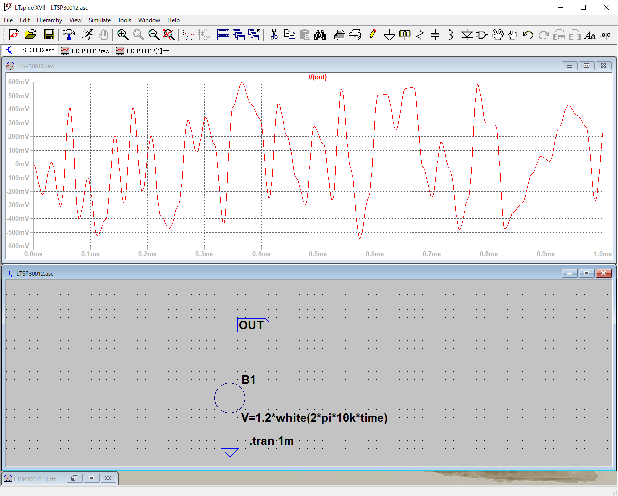
電流も流すように、0.47μFのコンデンサと10kΩの抵抗を追加しました。
シミュレーション時間をもう少し延ばして300msして結果を次に示します。ピーク値は±01.2V×0.5で、±0.6Vの範囲で振幅しています。
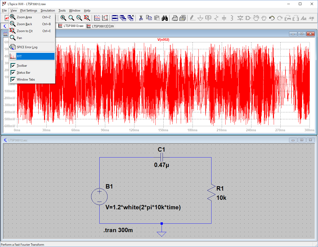
この出力波形の周波数成分を調べるために、FFT(fast Fourier transform)で実際の出力波形の周波成分を調べます。
グラフの画面を選択し、メニューバーのViewを選択し、次に示すようにリストのFFTを選択します。
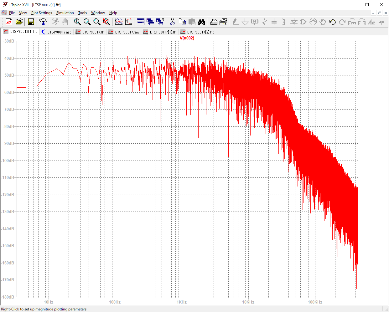
このシミュレーション結果をFFTにより周波数解析を行います。次に示すよう10kHz位まで水平方向に同じレベルとなっています。この範囲にはほぼ均等に各周波数の成分が含まれていることが確認できます。10kHz以上の周波数のレベルは大幅に減少しているのがはっきり認められます。
●シミュレーション結果をWaveファイルに
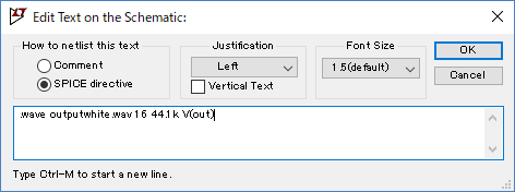
シミュレーション結果をWaveファイルに出力して、その音を聞いてみます。
次に示すように.Waveディレクティブで出力ファイルを指定し、音の状態がわかるようにシミュレーション時間を10sに設定しました。
シミュレーション結果は次のようになります。少し時間がかかります。
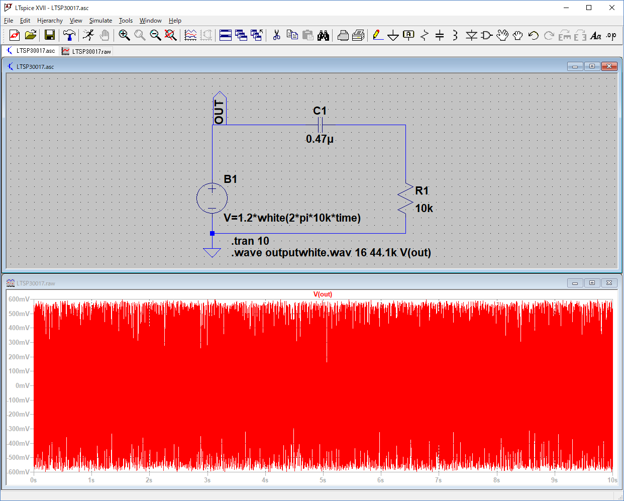
Waveファイルを再生するとザーというホワイト・ノイズが聞こえてきます。
(2018/4/10 V1.0)
<神崎康宏>