Raspberry Pi Picoでプログラミング ⑪ i2c 温度センサTMP117
温度センサTMP117は、動作温度範囲;-55~+150℃で、確度;-20~+50℃の範囲で±0.1℃(最大値)と、小数点第一位までが信頼できます。読み出すデータは16ビットで0.0078125°C (1LSB)の分解能があります。
●温度センサTMP117のおもなスペック
- 電源電圧 1.8~5.5V
- 消費電流 135µA(変換時のみ)
- 測定温度範囲 -40~125℃。0.007815℃ の分解能(16 ビット)で±0.1℃ (+20~+50℃、8回平均、1Hz繰り返し)の確度
- インターフェース I2C(1~400kHz)
- データ長 2の補数形式の16ビット
- I2Cスレーブ・アドレス ADD0の接続先で0x48~0x4bの範囲に設定できる
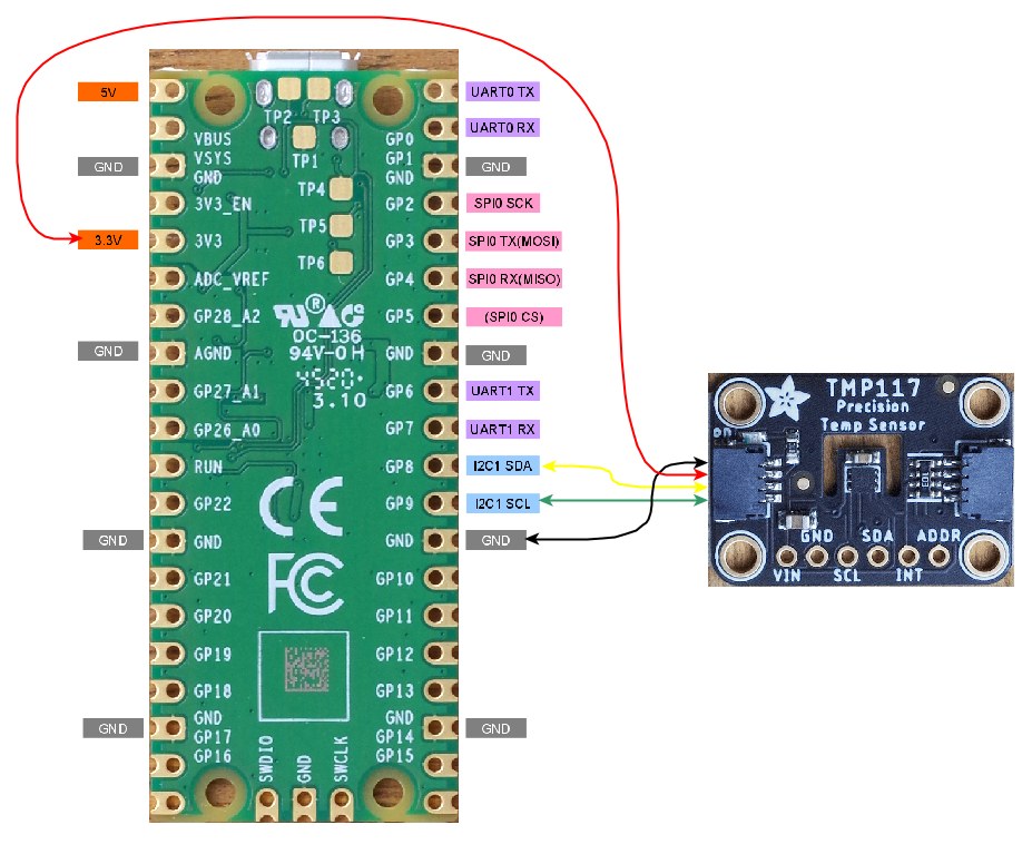
●接続
Adafruitのブレークアウト・ボードを利用します。
[GP9,GP8]のi2c0バスにつなぎます。このボードはSTEMMA QTと呼ばれるI2C専用の4ピンコネクタがついています。2本の信号線以外に、3.3VとGNDをつなぎます。
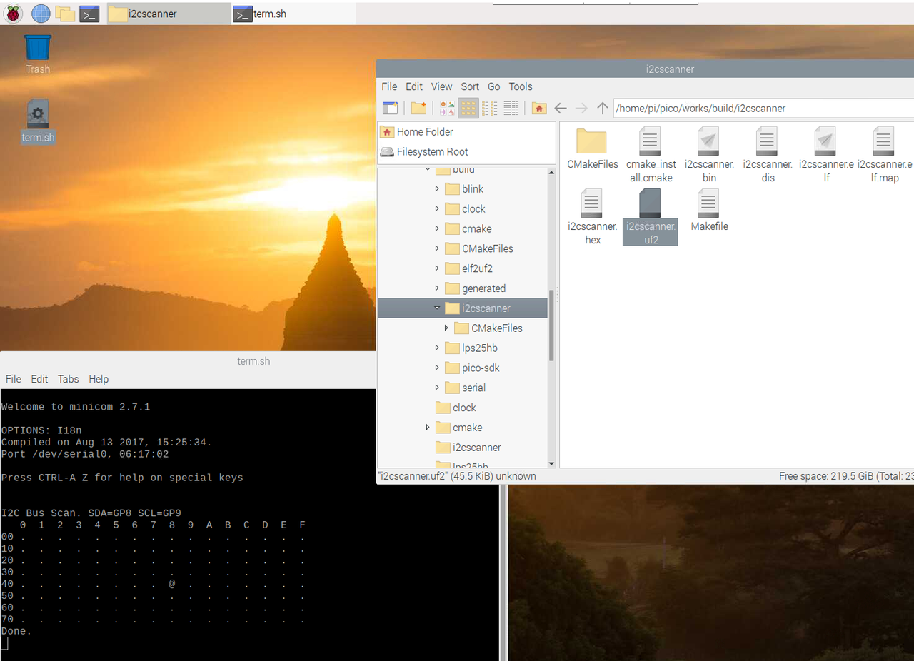
●i2cscannerでスレーブ・アドレスを確認
デフォルトの0x48です。
●主なレジスタ
温度データは読み出し専用です。コンフィギュレーションのデフォルト0x0220は、測定を8回して平均を求め、1Hzの変換時間の設定です。
| ポインタ・ レジスタ |
機能 | 初期値 |
|---|---|---|
| 0x00 | 温度データ | 0x8000 |
| 0x01 | コンフィギュレーション | 0x0220 |
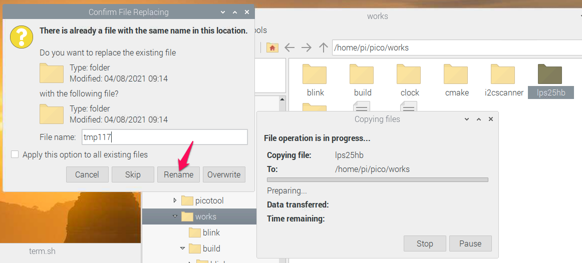
●lps25hbをコピーしてくる
前回作成したlps25hbのフォルダをコピーします。ペーストするときに、renameしてtmp117にします。
pico/worksにあるCMakeLists.txtを次のように修正します。
cmake_minimum_required(VERSION 3.12)

# Pull in SDK (must be before project)
include(pico_sdk_import.cmake)

project(pico_examples C CXX ASM)
set(CMAKE_C_STANDARD 11)
set(CMAKE_CXX_STANDARD 17)

set(PICO_EXAMPLES_PATH ${PROJECT_SOURCE_DIR})

# Initialize the SDK
pico_sdk_init()

# Add blink example
add_subdirectory(cmake)
add_subdirectory(blink)
add_subdirectory(serial)
add_subdirectory(clock)
add_subdirectory(i2cscanner)
add_subdirectory(lps25hb)
add_subdirectory(tmp117)
pico/works/tmp117のCMakeLists.txtを次のように修正します。
add_executable(tmp117
        tmp117.c
        )

# Pull in our pico_stdlib which pulls in commonly used features
target_link_libraries(tmp117 pico_stdlib hardware_i2c)

# create map/bin/hex file etc.
pico_add_extra_outputs(tmp117)
ソースのlps25hb.cをtmp117.cにrenameし、次のように修正します。ConfigurationRegisterの内容を、測定を8回から32回して平均を求める指示に変更しました。
#include
#include "pico/stdlib.h"
#include "hardware/i2c.h"
static int tmp117_addr = 0x48;
#define I2C_PORT i2c0
#define TemperatureRegister 0x00
#define ConfigurationRegister 0x01
#define READ_BIT 0x80
#define SDA_PIN 8 // GP8
#define SCL_PIN 9 // GP9
static void write_register16(uint8_t reg, uint8_t data0, uint8_t data1) {
uint8_t buf[3];
buf[0] = reg; buf[1] = data0; buf[2] = data1;
i2c_write_blocking(I2C_PORT, tmp117_addr, buf, 3, true);
}
static int32_t tmp117_read_raw() {
uint8_t buffer[2];
uint8_t val = TemperatureRegister | READ_BIT;
i2c_write_blocking(I2C_PORT, tmp117_addr, &val, 1, true);
i2c_read_blocking(I2C_PORT, tmp117_addr, buffer, 2, false);
int16_t temp = buffer[0] << 8 | buffer[1];
return ( -(temp & 0b1000000000000000) | (temp & 0b0111111111111111) );
}
int main() {
stdio_init_all();
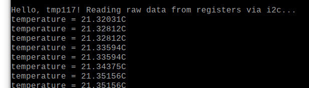
printf("\nHello, tmp117! Reading raw data from registers via i2c...\n");
// setup i2c
int f = i2c_init(I2C_PORT, 400 * 1000);
gpio_set_function(SDA_PIN, GPIO_FUNC_I2C);
gpio_set_function(SCL_PIN, GPIO_FUNC_I2C);
gpio_pull_up(SDA_PIN);
gpio_pull_up(SCL_PIN);
// Configuration
write_register16(ConfigurationRegister, 0x00, 0x60);
while (1) {
int32_t temperature = tmp117_read_raw();
printf("temperature = %.5fC\n", temperature * 7.8125 /1000.0);
sleep_ms(1000);
}
return 0;
}
ターミナルを開き、~pico/works/buildまでおります。
cmake ..
終了したら、tmp117ディレクトリにおります。
make -j4
●標準入出力を起動
デスクトップに置いてあるterm.shのアイコンをダブルクリックして立ち上げます。
Resetボタンを押したまま、BOOTSELボタンを押し、Resetボタンを離してから、BOOTSELボタンを離します。RPI-RP2ドライブがマウントができます。
tmp117.uf2を、RPI-RP2ドライブにドロップします。