Raspberry Pi Picoでプログラミング ⑫ i2c 湿度センサAHT20
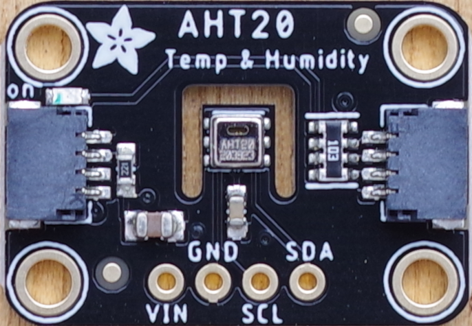
低価格湿度センサのAHT20をつなぎました。使用したAdafruitのブレークアウト・ボードは、STEMMA QT(JST SH 4ピン)コネクタは2か所に装着されていて、どちらにつないでもかまいません。このコネクタを使ってI2Cで制御する場合、特に、ジャンパ線をつなぐなどは不要です。
●湿度センサAHT20のおもなスペック
- 電源電圧 2.0~5.5V
- 湿度 確度±2%RH、分解能0.024%RH
- 温度 確度±0.3℃、分解能0.01℃
- インターフェース I2C(0~400kHz)
- スレーブ・アドレス 0x38(固定)
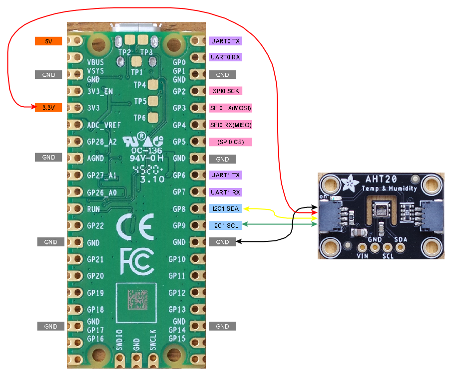
●接続
Adafruitのブレークアウト・ボードを利用します。
[GP9,GP8]のi2c0バスにつなぎます。このボードはSTEMMA QTと呼ばれるI2C専用の4ピンコネクタがついています。2本の信号線以外に、3.3VとGNDをつなぎます。
●tmp117のフォルダをコピーして使う
前回作成したtmp117のフォルダをコピーし、フォルダ名をaht20に変更します。
/poco/worksにあるCMakeLists.txtを次のように修正します。
cmake_minimum_required(VERSION 3.12)

# Pull in SDK (must be before project)
include(pico_sdk_import.cmake)

project(pico_examples C CXX ASM)
set(CMAKE_C_STANDARD 11)
set(CMAKE_CXX_STANDARD 17)

set(PICO_EXAMPLES_PATH ${PROJECT_SOURCE_DIR})

# Initialize the SDK
pico_sdk_init()

# Add blink example
add_subdirectory(cmake)
add_subdirectory(blink)
add_subdirectory(serial)
add_subdirectory(clock)
add_subdirectory(i2cscanner)
add_subdirectory(lps25hb)
add_subdirectory(tmp117)
add_subdirectory(aht20)
/poco/works/aht20にあるCMakeLists.txtを次のように修正します。
add_executable(aht20
        aht20.c
        )

# Pull in our pico_stdlib which pulls in commonly used features
target_link_libraries(aht20 pico_stdlib hardware_i2c)

# create map/bin/hex file etc.
pico_add_extra_outputs(aht20)
tmp117.cはaht20.cに変更し、内容を次のように書き換えます。
#include <stdio.h>
#include "pico/stdlib.h"
#include "hardware/i2c.h"

static int aht20_addr = 0x38;

#define I2C_PORT  i2c0

#define SDA_PIN 8  // GP8
#define SCL_PIN 9  // GP9

static void write_register16(uint8_t reg, uint8_t data0, uint8_t data1) {
    uint8_t buf[3];
    buf[0] = reg; buf[1] = data0; buf[2] = data1;
    i2c_write_blocking(I2C_PORT, aht20_addr, buf, 3, false);
}

static void aht20_read_raw(uint32_t *humi, uint32_t *temp) {
    uint8_t buffer[7];
    i2c_read_blocking(I2C_PORT, aht20_addr, buffer, 7, false);
    *humi = (buffer[1] <<16 | buffer[2] << 8 | (buffer[3] >> 4 )) >> 4;
    *temp = (buffer[3] & 0x0f) << 16 | buffer[4] << 8 | buffer[5];
    // printf("\nhumi 0x%x 0x%x 0x%x\n", buffer[1],buffer[2],buffer[3]);
    // printf("\ntemp 0x%x 0x%x 0x%x\n", buffer[3],buffer[4],buffer[5]);
    printf("\ncrc 0x%x\n", buffer[6]);
}

int main() {
    stdio_init_all();

    printf("\nHello, aht20! Reading raw data from registers via i2c...\n");

    // setup i2c
    int f = i2c_init(I2C_PORT, 400 * 1000);
    gpio_set_function(SDA_PIN, GPIO_FUNC_I2C);
    gpio_set_function(SCL_PIN, GPIO_FUNC_I2C);
    gpio_pull_up(SDA_PIN);
    gpio_pull_up(SCL_PIN);

    // calibration
    write_register16(0xbe, 0x08, 0x00);
    sleep_ms(10);

     uint32_t humi, temp;

    while (1) {
        // trigger measurement
        write_register16(0xac, 0x33, 0x00);
        sleep_ms(80);
        aht20_read_raw(&humi, &temp);
        printf("humidity = %.1f%\n", (float)humi * 100 / 1048576);
        printf("temperature = %.2fC\n", ((float)temp * 200 / 1048576) - 50);
        sleep_ms(1000);
    }

    return 0;
}
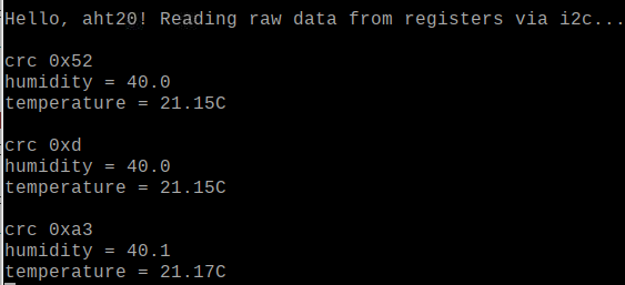
実行結果です。
●CRC8の計算
読み出した、ステータス、湿度、温度の6バイトの後ろにCRCデータが送られてきています。6バイトを読んでCRC8を計算します。
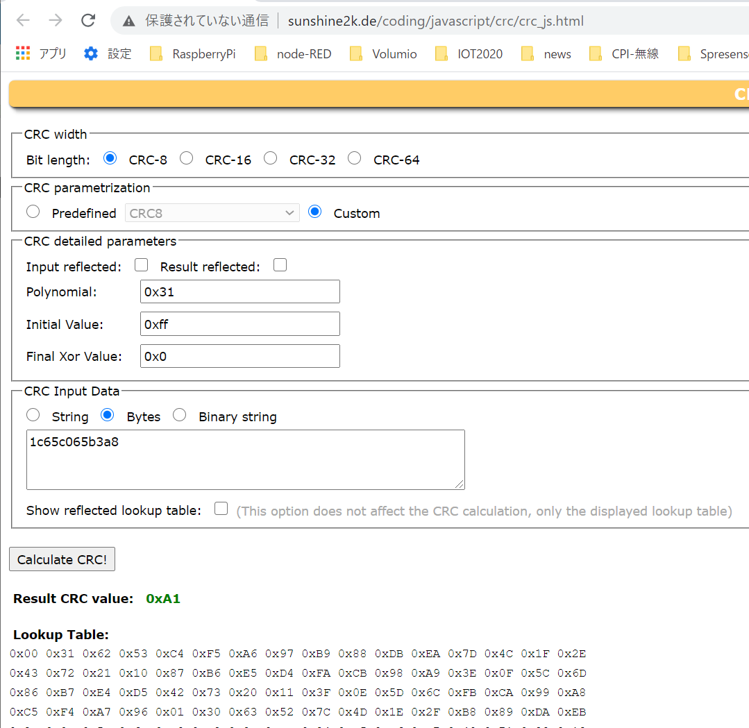
CRCは、PolynomialがCRC[7:0]=1+x4+x5+x8 のDallas/MaximのCRC8です。初期値は0xffです。読み出したcrc値と計算したcrc値を表示しました。近距離では双方の値が異なることはありません。通信距離が長いとか、ノイズが多い環境のとき、不一致だとデータを捨てるような使いかたになると思います。
#include <stdio.h>
#include "pico/stdlib.h"
#include "hardware/i2c.h"

static int aht20_addr = 0x38;

#define I2C_PORT  i2c0

#define SDA_PIN 8  // GP8
#define SCL_PIN 9  // GP9

static void write_register16(uint8_t reg, uint8_t data0, uint8_t data1) {
    uint8_t buf[3];
    buf[0] = reg; buf[1] = data0; buf[2] = data1;
    i2c_write_blocking(I2C_PORT, aht20_addr, buf, 3, false);
}

uint8_t CalcCrc(uint8_t data[6]) {
    uint8_t crc = 0xFF;
    for(int i = 0; i < 6; i++) {
        crc ^= data[i];
        for(uint8_t bit = 8; bit > 0; --bit) {
            if(crc & 0x80) {
                crc = (crc << 1) ^ 0x31u;
            } else {
                crc = (crc << 1);
            }
        }
    }
    return crc;
}

static void aht20_read_raw(uint32_t *humi, uint32_t *temp) {
    uint8_t buffer[7];
    i2c_read_blocking(I2C_PORT, aht20_addr, buffer, 7, false);
    *humi = (buffer[1] <<16 | buffer[2] << 8 | (buffer[3] >> 4 )) >> 4;
    *temp = (buffer[3] & 0x0f) << 16 | buffer[4] << 8 | buffer[5];
    printf("\nstatus 0x%x\n", buffer[0]);
    printf("\nhumi 0x%x 0x%x 0x%x\n", buffer[1],buffer[2],buffer[3]);
    printf("\ntemp 0x%x 0x%x 0x%x\n", buffer[3],buffer[4],buffer[5]);
    printf("\ncrc read 0x%x\n", buffer[6]);
    uint8_t data[6];
    data[0] = buffer[0]; data[1] = buffer[1];data[2] = buffer[2]; data[3] = buffer[3];data[4] = buffer[4]; data[5] = buffer[5];
    uint8_t crc8 = CalcCrc(data);
    printf("crc calc 0x%x\n", crc8);
}


int main() {
    stdio_init_all();

    printf("\nHello, aht20! Reading raw data from registers via i2c...\n");

    // setup i2c
    int f = i2c_init(I2C_PORT, 400 * 1000);
    gpio_set_function(SDA_PIN, GPIO_FUNC_I2C);
    gpio_set_function(SCL_PIN, GPIO_FUNC_I2C);
    gpio_pull_up(SDA_PIN);
    gpio_pull_up(SCL_PIN);

    // calibration
    write_register16(0xbe, 0x08, 0x00);
    sleep_ms(10);

     uint32_t humi, temp;

    while (1) {
        // trigger measurement
        write_register16(0xac, 0x33, 0x00);
        sleep_ms(80);
        aht20_read_raw(&humi, &temp);
        printf("humidity = %.1f%%\n", (float)humi * 100 / 1048576);
        printf("temperature = %.2fC\n", ((float)temp * 200 / 1048576) - 50);
        sleep_ms(10000);
    }

    return 0;
}
実行結果です。
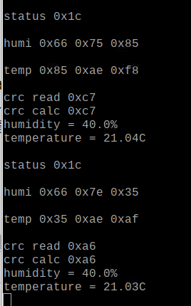
表示されたstatusからtempの6バイトをこちらのサイトに入力して、計算が正しいかをチェックしました。